Shielded connector

Inactive Publication Date: 2009-02-05
SUMITOMO WIRING SYST LTD
View PDF11 Cites 35 Cited by
  • Summary
  • Abstract
  • Description
  • Claims
  • Application Information

AI Technical Summary

Benefits of technology

[0007]The invention relates to a shielded connector with at least one terminal fitting to be connected with an end of a core of a shielded cable. The shielded connector also has a housing for accommodating the terminal fitting, and a shielding shell that can be mounted to the housing for contacting a shielding portion of the shielded cable. The shielding shell defines a tubular shape surrounding the outer si

Problems solved by technology

However, external matter can interfere with outwardly projecting parts of the spring pieces.
Thus, the spring pieces easi

Method used


Image

  • Shielded connector
  • Shielded connector
  • Shielded connector

Examples


Example

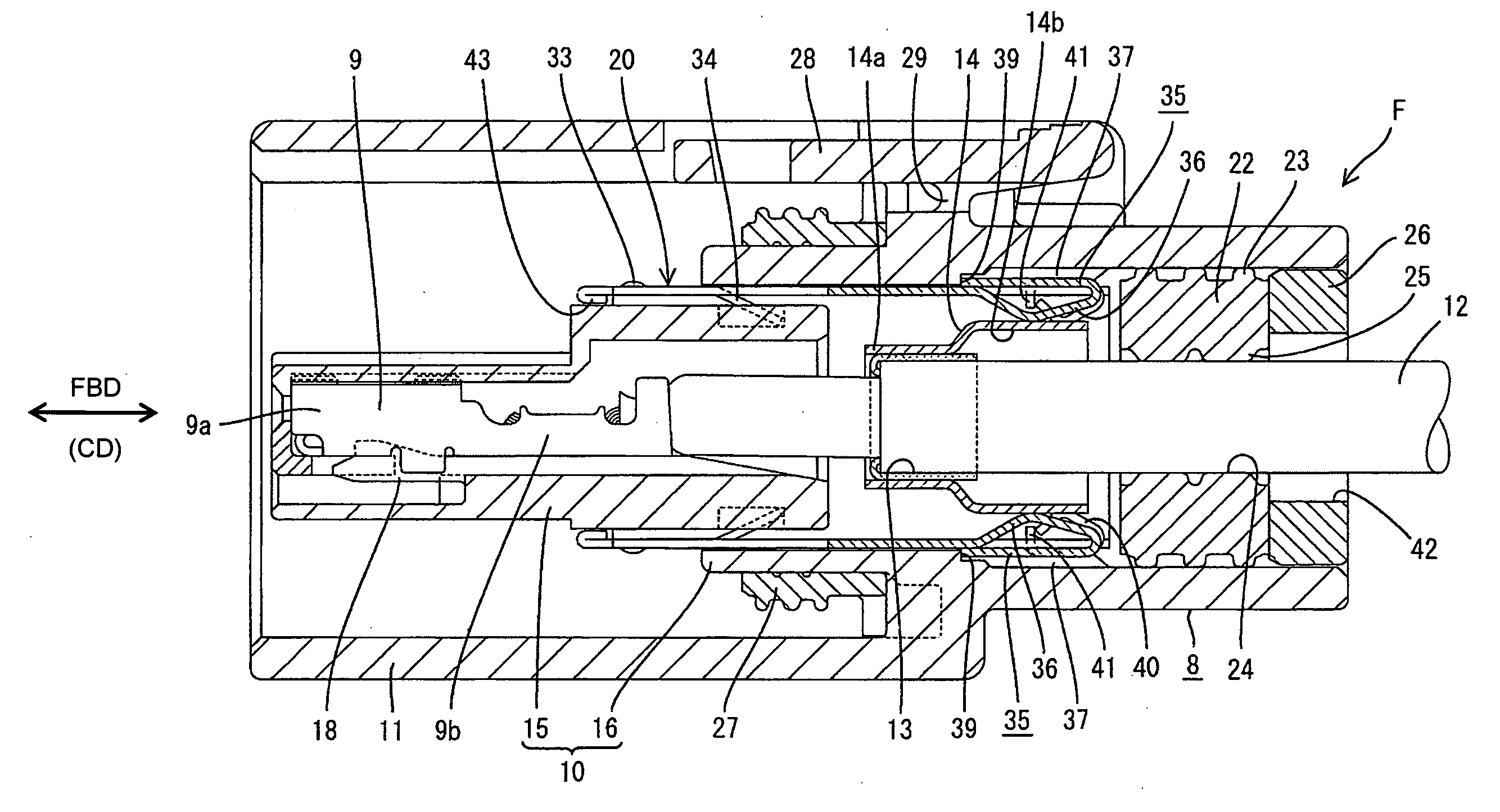
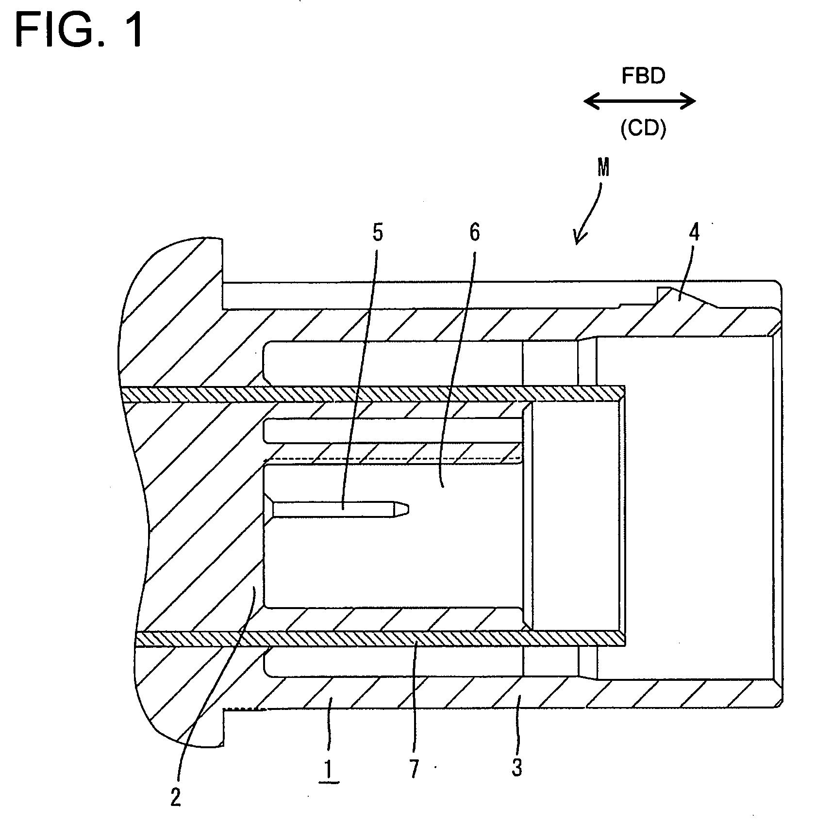
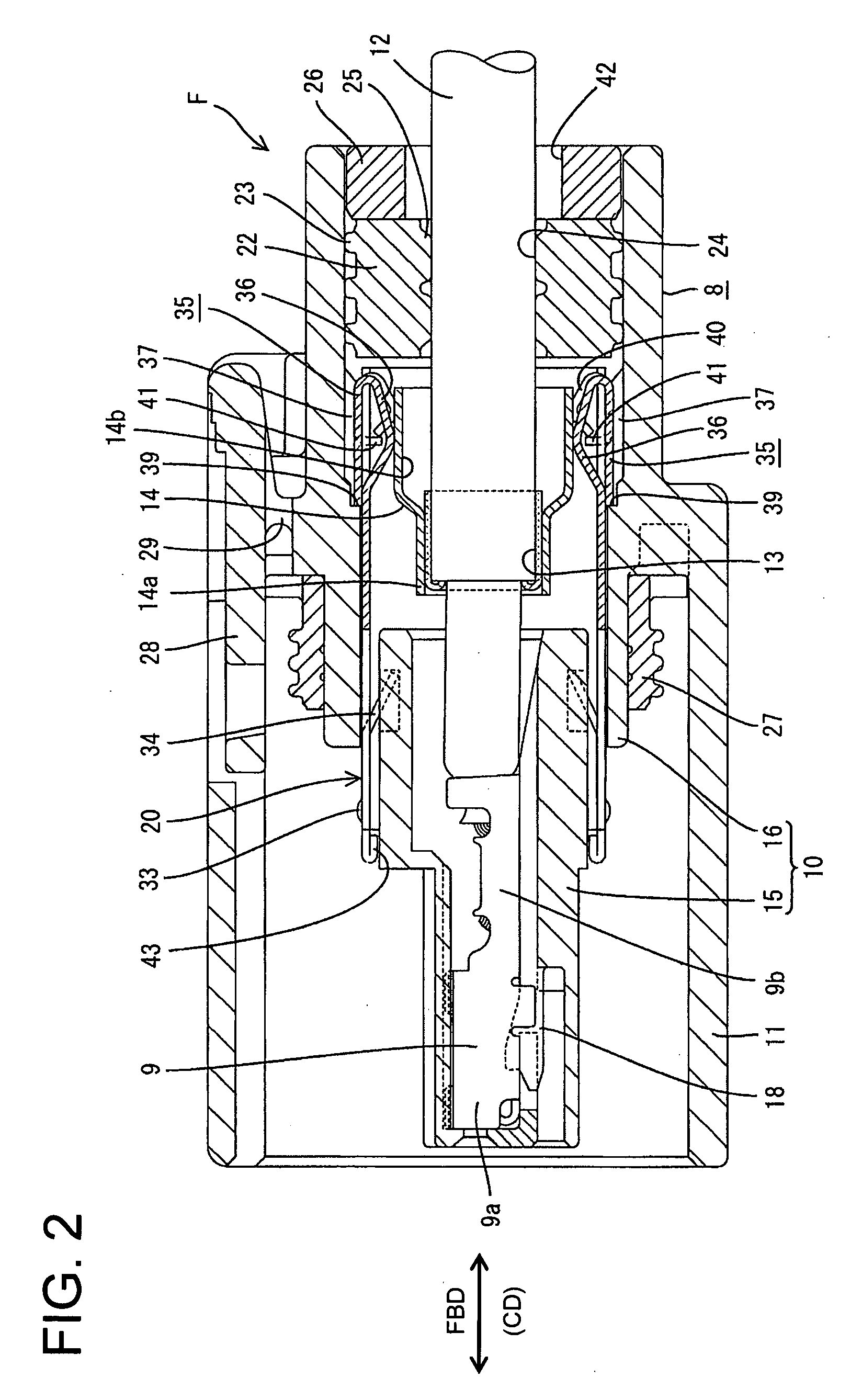
[0026]Male and female connectors according to a first embodiment of the invention are identified respectively by the letters M and F in FIGS. 1 to 6. Connection ends of the male and female connectors M and F along a connecting direction CD are referred to herein as the front ends.

[0027]The male connector M includes a housing 1 made e.g. of a synthetic resin. A terminal accommodating portion 2 is provided inside the housing 1 for accommodating male terminal fittings and a rectangular tubular receptacle 3 at least partly surrounding the terminal accommodating portion 2. A lock 4 projects in an intermediate part of the upper surface of the receptacle 3 near the opening edge, and is used to lock the connected state with a female connector F. Tabs 5 of male terminal fittings project forward from the back wall of the terminal accommodating portion 2. In this embodiment, two male terminal fittings are arranged side by side with a partition wall 6 interposed therebetween. A shielding shell ...

Example

[0044]A second embodiment of the invention is described with reference to FIGS. 7 to 11. This embodiment differs from the first embodiment in the construction of the shielding shell of the female connector F and the crimp ring. Elements of the second embodiment that are similar to the first embodiment are identified by the same reference numerals, but are not described again.

[0045]The shielding shell of the second embodiment is identified by the numeral 50 and differs from the first embodiment primarily with respect to the touching portions 51. Two pairs of touching portions 51 are arranged substantially vertically symmetrically in the upper and lower walls of the shielding shell 50. Each touching portion 51 is formed between two slits 52 that are spaced apart in the width direction WD, and is resiliently deformable along the thickness direction. In other words, the touching portions 51 of this embodiment are formed to be substantially flush with the shielding shell 50. Lengthwise i...


PUM


Abstract

A crimp ring (14) is mounted on a braided wire (13) of a shielded cable (12). On the other hand, a shielding shell (20) connectable with a large diameter portion (14b) of the crimp ring (14) is mounted in a housing (8). Entire touching portions (35) are formed at both upper and lower surfaces of the shielding shell (20) by being bent inward to form mountain-shaped resilient contact pieces (36) that can resiliently contact the large diameter portion (14b) and then being folded back outward near the rear edge of the shielding shell (20). Displacement restricting portions (40) are arranged between the touching portions (35) adjacent in width direction to protect the other touching portions (35) from the interference of the shielded cable (12) being inserted or withdrawn.

Description

BACKGROUND OF THE INVENTION[0001]1. Field of the Invention[0002]The invention relates to a shielded connector.[0003]2. Description of the Related Art[0004]Japanese Unexamined Patent Publication No. H11-40273 discloses a conventional shielded connector with an electrical contact formed in a shielding shell. The contact can resiliently contact a shielding portion to achieve reliable and easy connection of a shielding portion of a shielded cable and the shielding shell.[0005]The shielding shell of the above-described connector is formed by bending an electrically conductive metal plate into a cylindrical shape, and four spring pieces project out in the longitudinal direction at regular angular intervals from the rear edge of the shielding shell. The spring pieces are folded in at the longitudinal projecting ends and can deform resiliently in radial directions. However, external matter can interfere with outwardly projecting parts of the spring pieces. Thus, the spring pieces easily can...

Claims


Application Information

Patent Timeline
IPC IPC(8): H01R9/03
CPCH01R4/185H01R9/0518H01R13/5804H01R13/5208H01R13/5219H01R13/4223
Inventor OKAYASU, YASUSHI
Owner SUMITOMO WIRING SYST LTD
Why Eureka
Try Eureka