Cam activated bicycle wheel brake

Inactive Publication Date: 2009-02-12
LIU ROBERT Z +1
View PDF2 Cites 39 Cited by
  • Summary
  • Abstract
  • Description
  • Claims
  • Application Information

AI Technical Summary

Benefits of technology

[0011]The brake of the invention is compact and lightweight in design. The brake maximiz

Problems solved by technology

Prior rim brakes suffer from a number of drawbacks.
Some brakes are very effective, but extremely heavy.
For example, some brakes are relatively lightweight but suffer from one or more disadvantages, such as requiring a high user application force or having an uneven braking action or poor braking force.
First, the configuration of the brake makes the brake large in dimension.
In this position, the arm (16) protrudes o

Method used


Image

  • Cam activated bicycle wheel brake
  • Cam activated bicycle wheel brake
  • Cam activated bicycle wheel brake

Examples


Embodiment Construction

[0018]In the following description, numerous specific details are set forth in order to provide a more thorough description of the present invention. It will be apparent, however, to one skilled in the art, that the present invention may be practiced without these specific details. In other instances, well-known features have not been described in detail so as not to obscure the invention.

[0019]One embodiment of the invention is a brake mechanism and, more particularly, a wheel brake. The invention has particular application to the wheel of a bicycle or similar apparatus or vehicle (unicycle, tricycle, etc.).

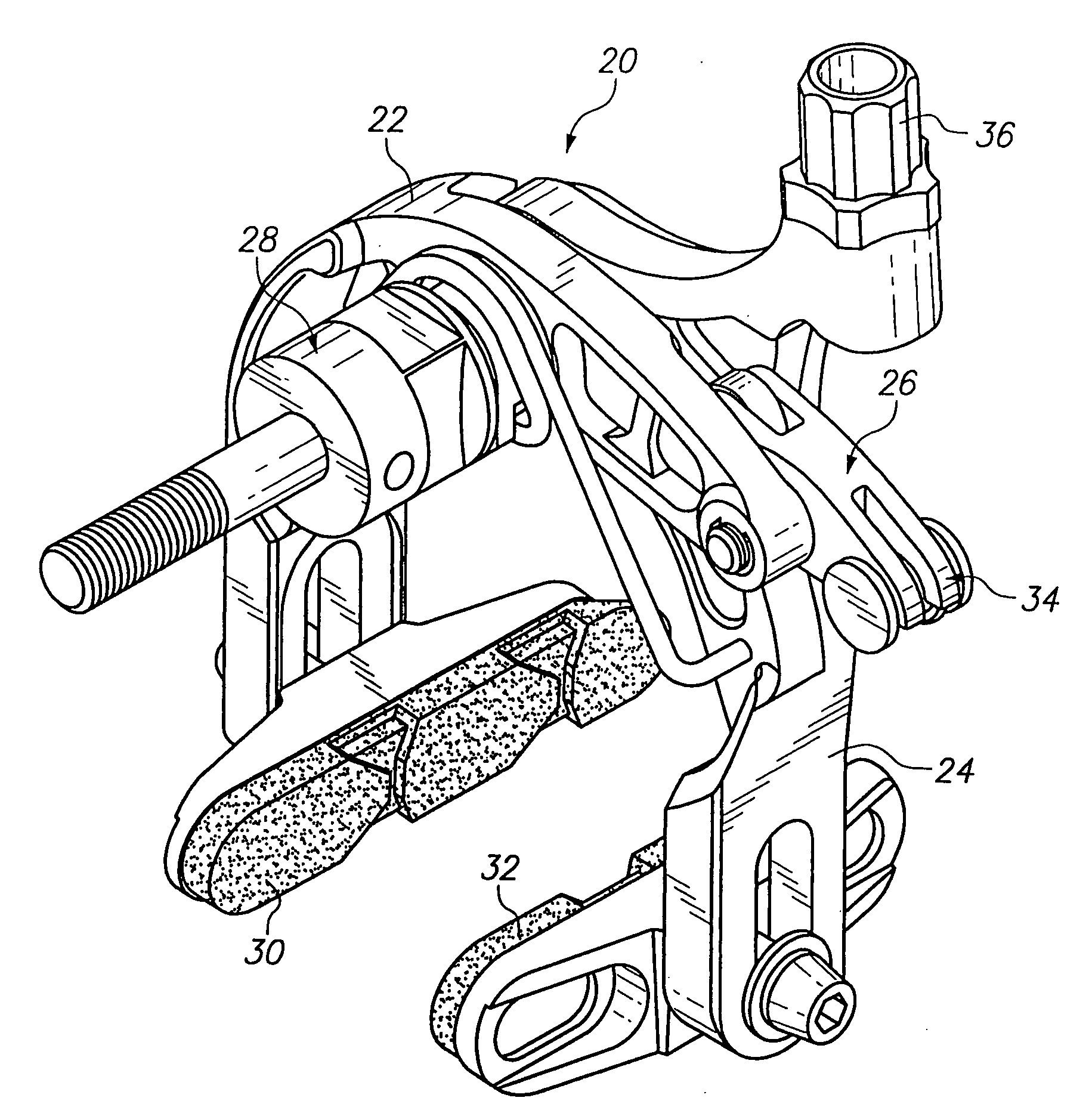
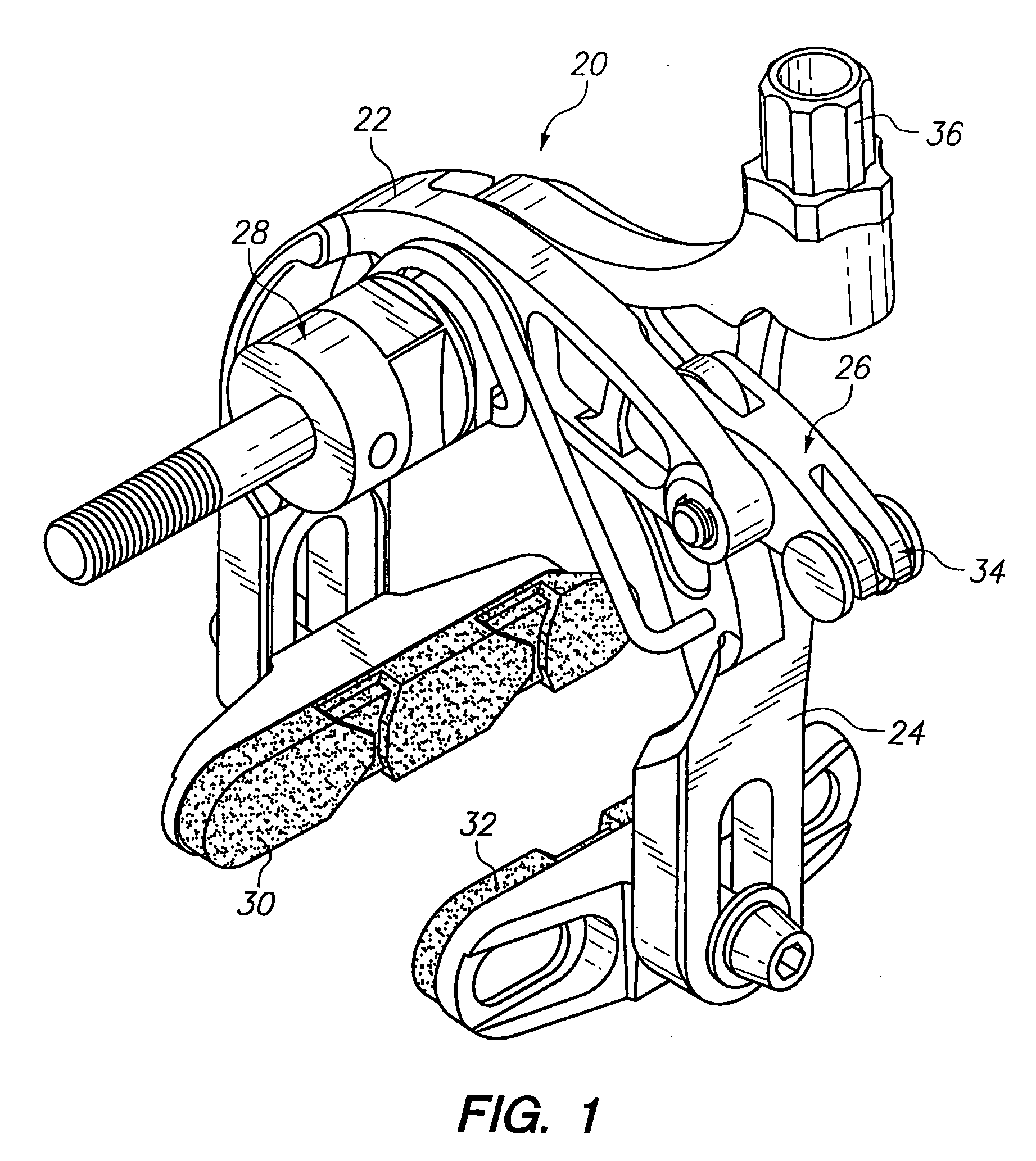
[0020]In general, the brake of the invention comprises a pair of arms configured to support brake pads for engaging a wheel. The arms are actuated by a cam. The cam may be actuated by a cable or similar device.

[0021]One embodiment of the invention will be described first with reference to FIG. 1. As illustrated therein, a brake or brake mechanism or device 20 comprises a first a...


PUM


Abstract

A wheel brake for a bicycle or other vehicle has a pair of pivoting arms. Each arm is configured to support a brake pad. A first arm pivotally supports a cam. A second arm defines a cam surface and a cable guide. The cam has a first end for mounting of a cable and a second end having a roller which rests on the cam surface. When the cable is actuated, the cable pulls the first end of the cam, causing the cam to pivot and causing the second end of the cam to roll along the cam surface. Force applied by the cam compresses the arms, causing associated brake pads to move inwardly into engagement with the wheel. The brake is compact and efficient in design.

Description

FIELD OF THE INVENTION[0001]The present invention relates to a braking mechanism for a bicycle wheel.BACKGROUND OF THE INVENTION[0002]A variety of brakes have been proposed for bicycles. These brakes include chain brakes, hub-mounted disc brakes, and the rim brake, among others. In general, rim brakes utilize one or more pads to press against the outer surface of the wheel rim adjacent the tire in order to generate a braking force.[0003]Prior rim brakes suffer from a number of drawbacks. First, it is desirable for the brake to be lightweight. Some brakes are very effective, but extremely heavy. Second, the brake must be reliable and effective in operation. For example, some brakes are relatively lightweight but suffer from one or more disadvantages, such as requiring a high user application force or having an uneven braking action or poor braking force.[0004]For example, U.S. Pat. No. 3,628,635 discloses a side-pull lever rim-type brake. As disclosed, the brake is constructed so tha...

Claims


Application Information

Patent Timeline
IPC IPC(8): B62L3/00
CPCB62L1/16B62L1/12
Inventor LIU, ROBERT Z.BARNETT, ROBERT L.
Owner LIU ROBERT Z
Why Eureka
Try Eureka