Sewage Treatment Process and System

a technology of sewage treatment and sewage treatment, applied in the direction of biological water/sewage treatment, water/sewage multi-stage treatment, separation process, etc., to achieve the effect of reducing construction space utilization, reducing water quality, and flexible control of sludge ag

Inactive Publication Date: 2012-01-26
SUN YOUFENG
View PDF7 Cites 67 Cited by
  • Summary
  • Abstract
  • Description
  • Claims
  • Application Information

AI Technical Summary

Benefits of technology

[0039]Compared to the prior art, the present invention can perform thorough solid-liquid separation of the mixed liquor in the biological reaction tank by the membrane separation device, can control sludge age more flexible. While the solid-liquid separation is performed in the prior art by gravitational sedimentation, in the case of long sludge age, it is easy to decrease the space utilization of the construction and even reduce water quality due to the high concentration of the sludge, high sludge interface, deterioration of the sludge settling characteristics. Therefore it can maximize the sludge concentration in the biological reaction tank, thus maximize biological nitrogen removal effect and the total amount of phosphorus released and the total amount of phosphorus absorbed by phosphorus accumulating organisms, the system can truly realize efficient removal of phosphorus without removing the excess activated sludge. This not only makes the system get the better effect of nitrogen and phosphorus removal, but also significantly reduces the production of excess activated sludge, and reduces the cost for sludge treatment and disposal.
[0040]Further, thoroughly processing solid-liquid separation of the mixed liquor in the biological reaction tank through the membrane separation device will enable effluent at the aerobic and anoxic stages to act as final discharged water for the system, with suspension in the effluent close to zero, this avoids the problem of high suspension amount in effluent which is generally exist in supernatant after sedimentation removal using a surface water removal device such as a decanter in the art, and eliminates excess phosphorus carried by the suspension in effluent, that is, solves the problem of exceed standard of total phosphorus concentration in effluent of sewage treatment system.
[0041]In addition, thoroughly processing solid-liquid separation with respect to the mixed liquor in the biological reaction tank through the membrane separation device will remove maximum phosphorus-enriched water formed from phosphorus accumulating organisms releasing phosphorus in anaerobic stage out of the system, and the effluent suspension formed by membrane separation is close to zero, so that the interference of suspension on phosphorus sedimentation when a flocculation sedimentation tank is used as the phosphorus recyling unit in the art is overcome, saving the amount of chemicals for phosphorus removal, reducing the chemical precipitate yield, increasing the phosphorus content in the phosphorus sedimentation, and creating a more advantageous condition for recycling phosphorus resource.
[0042]Further, in the present invention, aerobic, anoxic and anaerobic environments are carried out inside a single biological reaction tank sequentially in time order so as to achieve the removal of carbon, nitrogen and phosphorus simultaneously and efficiently, simplify the system in process, and eliminate an anaerobic phosphorus releasing tank compared with ERP-SBR system in the art, and eliminate four reactor and almost all of the recycle system compared with BCFS system. Therefore, under the premise of having the same nitrogen and phosphorus removal capacity, the sewage treatment system of the present invention uses a smaller site area, lower capital investment and operating costs and easier for management and maintenance.

Problems solved by technology

Eutrophication, which is mainly caused by the excessive emission of nutrients such as nitrogen, phosphorus and the like into the environment, is becoming a more and more serious, global environmental problem.
Due to relatively low concentration of nitrogen and phosphorus in municipal sewage and huge discharge of sewage, the removal of nitrogen and phosphorus by merely using physical and chemical methods has significant disadvantages of large amount of dosage, large amount of chemical precipitate, and high operation cost, and is seldom adopted in practical sewage treatment projects.
At present, the phenomena that nitrogen removal and phosphorus removal can not reach the best effect at the same time when applying a sewage biological nitrogen and phosphorus removal process, especially a multi-tank biological nitrogen and phosphorus removal system, in practice is often observed, that is, good nitrogen removal effect and poor phosphorus removal effect, or good phosphorus removal effect and poor nitrogen removal effect.
However, since the concentration of VFAs in municipal sewage is generally low (dozens mg / L), the competition caused by insufficient carbon source leads to that phosphorus accumulating bacteria are not dominant.
(4) Nitrate imposes adverse influence on the anaerobic phosphorus release.
Obviously, such method will lead to not only the increase in investment and operation cost of sewage treatment system, but also the increase in the number of the reactors and the return pipes.
However, the experiences in operation of a large number of biological phosphorus removal systemes both in China or aboard showed that, it is quite difficult to constantly keep a TP concentration of lower than 1 mg / L in discharged water.
However, the main flow path chemical phosphorus removal suffers from significant problems such as high amount of water to be treated, large dosage, high cost of agents, low agent utilization, large amount of precipitated sludge, low phosphorus content, difficulties in handling, inconvenient phosphorus recycling and reuse, and the like, therefore, it is difficult to be carried out in practical sewage treatment processes.
However, such process has very limited application up to now due to the following disadvantages: the process lacks nitrogen removal function; the phosphorus-enriched supernate in the anaerobic phosphorus release tank can be elutriated in a limited ratio by injecting elutriating water such as the discharged water from the initial sedimentation tank, the discharged water from the secondary sedimentation tank, or the supernate from the lime sedimentation reactor; substantial suspensions are remained in the supernate; the amount of the chemical precipitate is relatively high; and relatively high operation techniques of the process are required for the operator.
However, the BCFS process is extremely complicated, and involves in high infrastructure investment, high operation cost, large occupation, and complicated operation management.
Furthermore, the approach for removing phosphorus is mainly achieved by discharging phosphorus-enriched excess sludge, the on-line phosphorus separation and the off-line sedimentation of the anaerobic phosphorus-enriched sewage are only used as an assistant means, and the problems regarding the disposal of large amount of excess sludge and the recycling of the phosphorus resources from the sewage remain unresolved.
Therefore, the application of BCFS process in practical sewage treatment project is significantly limited.
However, ERP-SBR process still has the following disadvantages: (1) the controlling of the sludge age is in dilemma: shortening sludge age is not advantageous for the reason of disfavoring biological nitrogen removal and increasing the disposal cost of the sludge, while prolonging the sludge age can maximally recover and reuse the phosphorus in the sewage as phosphorus-enriched sedimentation; however, prolonging the sludge age will gradually increase the concentration of the sludge in SBR reactor serving as the main reacting tank as the run time is lengthened, the efficiency of sludge-water separation due to gravity sedimentation is gradually decreased, the surface of the sludge is lifted, and the volumetric exchange ratio of the SBR reactor is reduced, which further decrease the space utilization of the SBR reactor, and even cause sludge bulking and degradation in water quality of the discharged water in serious situation; (2) using a decanter as the water decanting device for decanting the supernate at the end of sedimentation in the SBR reactor as the final discharged water, the SS (solid suspension) in the discharged water is difficult to be decreased below 10 mg / L; and the TP carried in the SS in the discharged water is usually 0.5 mg / L since the phosphorus content of the SS in the supernate at the end of the sedimentation in the SBR reactor is generally no less than 5%, so that the discharge of the whole system can hardly meet the requirements about TP as stated in Level A standard of GB18918; (3) the process of anaerobic phosphorus release is short itself, generally about 2 h, however, in the case of high sludge concentration, the sludge-water separation by means of gravity sedimentation in the anaerobic phosphorus release tank needs long precipitating time, and lifts the sludge surface, so that the discharging height of the phosphorus-enriched supernate that can be discharged into the chemical phosphorus removal tank is greatly reduced.
Even if the anaerobic phosphorus release has been sufficiently finished, the phosphorus-enriched supernate that can be efficiently discharged into the chemical phosphorus removal tank is less than half of the total phosphorus-enriched sewage, so that the phosphorus removal ability of the system can not be further improved.

Method used


Image

  • Sewage Treatment Process and System
  • Sewage Treatment Process and System
  • Sewage Treatment Process and System

Examples


example 1

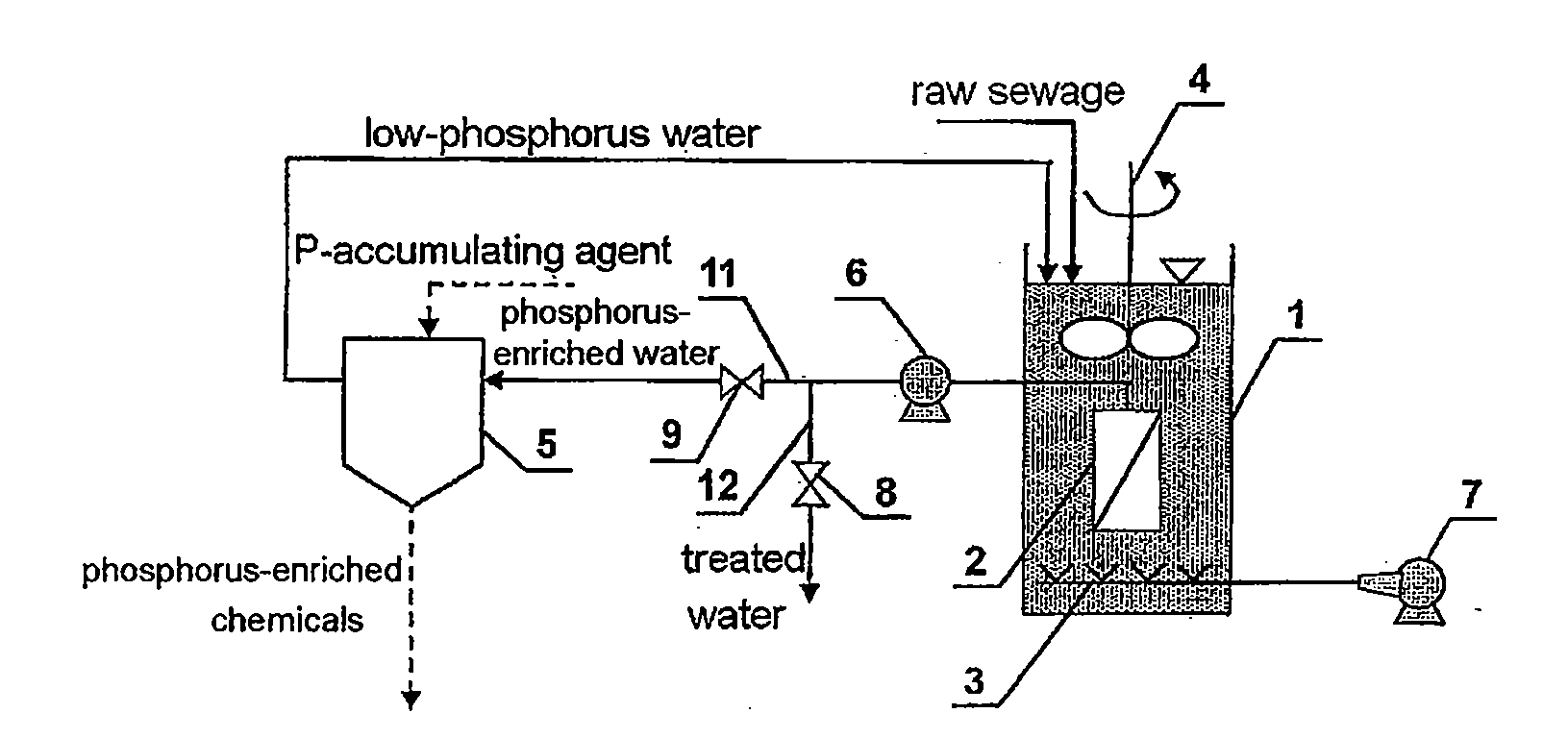
[0100]As shown in FIG. 4a, a sewage treatment system comprises a biological reaction tank 1, a membrane separation device 2 installed inside the biological reaction tank 1, an aeration device 3 and a stirring device 4, a phosphorus recyling unit 5 installed outside the biological reaction tank 1, a suction pump 6 whose suction port is communicated to water outlet of the membrane separation device 2, a blower whose gas outlet is communicated to the gas inlet of the aeration device 3. The pipeline communicated to the water outlet of the suction pump 6 is divided into two branch pipelines, i.e. the first aqueduct 11 and the second aqueduct 12, wherein the first aqueduct 11 is communicated to a produced water collecting device, the second aqueduct 12 is communicated to the water inlet of the phosphorus recyling unit 5 whose water outlet is communicated to the biological reaction tank 1 by pipeline. An electrically operated valve is installed on each of the first aqueduct 11 and the seco...

example 2

[0108]As shown in FIG. 4b, a sewage treatment system is provided, most structures of which are the same as the Example 1, except that the membrane separation device 2 is disposed outside of the biological reaction tank 1, the biological reaction tank 1 and the membrane separation device 2 are communicated through liquor supply pipe 25 and liquor backflow pipe 26, wherein circulating pumps 10 is disposed on the liquor supply pipe 25. There are 6 circulating pumps 10, four in use and two for backup, the flow rate of each one being 800 m3 / h, the pump lift thereof being 12 m, and the power thereof being 45 kW. No suction pump is provided in the sewage treatment system of the invention, and the pre-treat device at the early stage thereof is the same as that in Example 1.

[0109]There 200 members of membrane separation device 2 which are divided into 4 groups, 50 for each group. Every group is arranged in two rows each having 25 devices. The contour dimension of each membrane separation dev...

example 3

[0113]As shown in FIG. 4c, a sewage treatment system is provided, most structures of which are the same as the Example 1, except that the membrane separation device 2 is disposed in membrane filter tank 13 which is independent from the biological reaction tank 1, and aeration device 3 are arranged in both the biological reaction tank 1 and the membrane filter tank 13, while the stirring device 4 is disposed only in the biological reaction tank 1. The biological reaction tank 1 and the membrane filter tank 13 are communicated through a liquor supply pipe 25 and a liquor backflow pipe 26, wherein a circulating pumps 10 is disposed on the liquor backflow pipe 26. There are 6 circulating pumps 10, four in use and two for backup, the flow rate of each one being 800 m3 / h, the pump lift thereof being 12 m, and the power thereof being 45 kW. The pipeline communicated to the gas outlet of the blower 7 is divided into two branch pipelines, one of which is communicated to the aeration device 3...


PUM

PropertyMeasurementUnit
concentrationaaaaaaaaaa

Abstract

A sewage treatment process is provided, which includes the following steps: a) sewage feeding step, comprising introducing raw sewage into a biological reaction tank (1) to a predetermined time or liquid level; b) reaction step comprising performing aeration and stirring intermittently in the biological reaction tank (1); c) treated water discharging step, comprising performing solid-liquid separation of the mixed liquor in the biological reaction tank (1) by a membrane separation device (2) to obtain a first permeate, which is taken as the final treated water; d) standby step comprising stopping aeration in the biological reaction tank (1); and e) phosphorus-enriched water discharging step, comprising keeping anaerobic condition in the biological reaction tank (1) and performing solid-liquid separation of the mixed liquor in the biological reaction tank (1) by a membrane separation device (2) to obtain a second permeate, the second permeate entering inside a phosphorus recycling unit (5) which is set independent from the biological reaction tank (1), the phosphorus recycling unit (5) removing phosphorus from water, the second permeate becoming low-phosphorus water, and the low-phosphorous water flowing back to the biological reaction tank (1); the sewage treatment process runs in cycle by repeating above steps. A corresponding treatment system is also provided.

Description

[0001]This application claims priority to Chinese Patent Application No. 200910081502.0 filed with the State Chinese Intellectual Property Office of China on Apr. 9, 2009, entitled “PROCESS AND SYSTEM FOR TREATING SEWAGE”, which is hereby incorporated by reference.FIELD OF THE INVENTION[0002]The present invention relates to a sewage treatment process and system, which is particularly suitable for treating municipal sewage, pertaining to the field of water treatment technology.BACKGROUND ART[0003]Eutrophication, which is mainly caused by the excessive emission of nutrients such as nitrogen, phosphorus and the like into the environment, is becoming a more and more serious, global environmental problem. As a result, the countries in the world are all upgrading the sewage discharge standard thereof. According to standard A in Level I standard in the current national standard Discharge Standard of Pollutants for Municipal Sewage Treatment Plant (GB 18918-2002), the amount of discharged a...

Claims


Application Information

Patent Timeline
Patent Type & Authority Applications(United States)
IPC IPC(8): C02F9/14C02F1/44C02F1/66C02F1/42C02F1/28C02F1/52C02F1/24C02F11/04C02F1/72C02F1/461C02F1/30C02F1/50C02F1/78C02F3/32C02F1/469C02F3/30
CPCC02F3/1215C02F3/1273C02F3/301C02F3/1263C02F2209/42C02F2209/44C02F3/308Y10S210/906Y02W10/10
Inventor SUN, YOUFENGQIAN, JUE
Owner SUN YOUFENG
Why Eureka
Try Eureka