Method of fabricating case, piezoelectric oscillator, oscillator, electronic appliance, and radio clock
a piezoelectric oscillator and piezoelectric technology, applied in the field of fabricating cases, piezoelectric oscillators, oscillators, electronic appliances, radio clocks, can solve the problems of reducing stiffness, unable to maintain themselves in parallel state, and likely deformation of leads in the fabrication process, so as to facilitate manufacture and reduce size , the effect of radio clock
- Summary
- Abstract
- Description
- Claims
- Application Information
AI Technical Summary
Benefits of technology
Problems solved by technology
Method used
Image
Examples
first embodiment
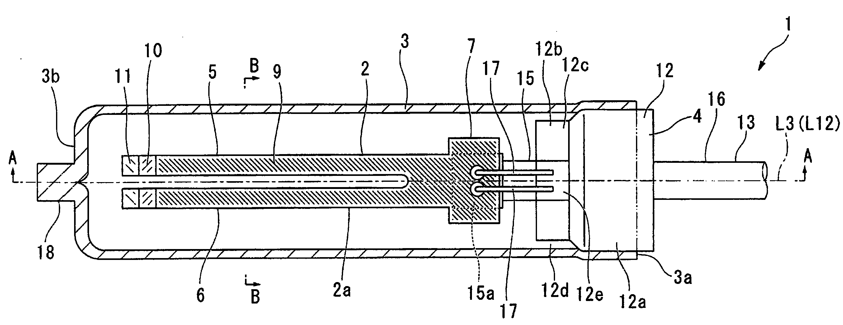
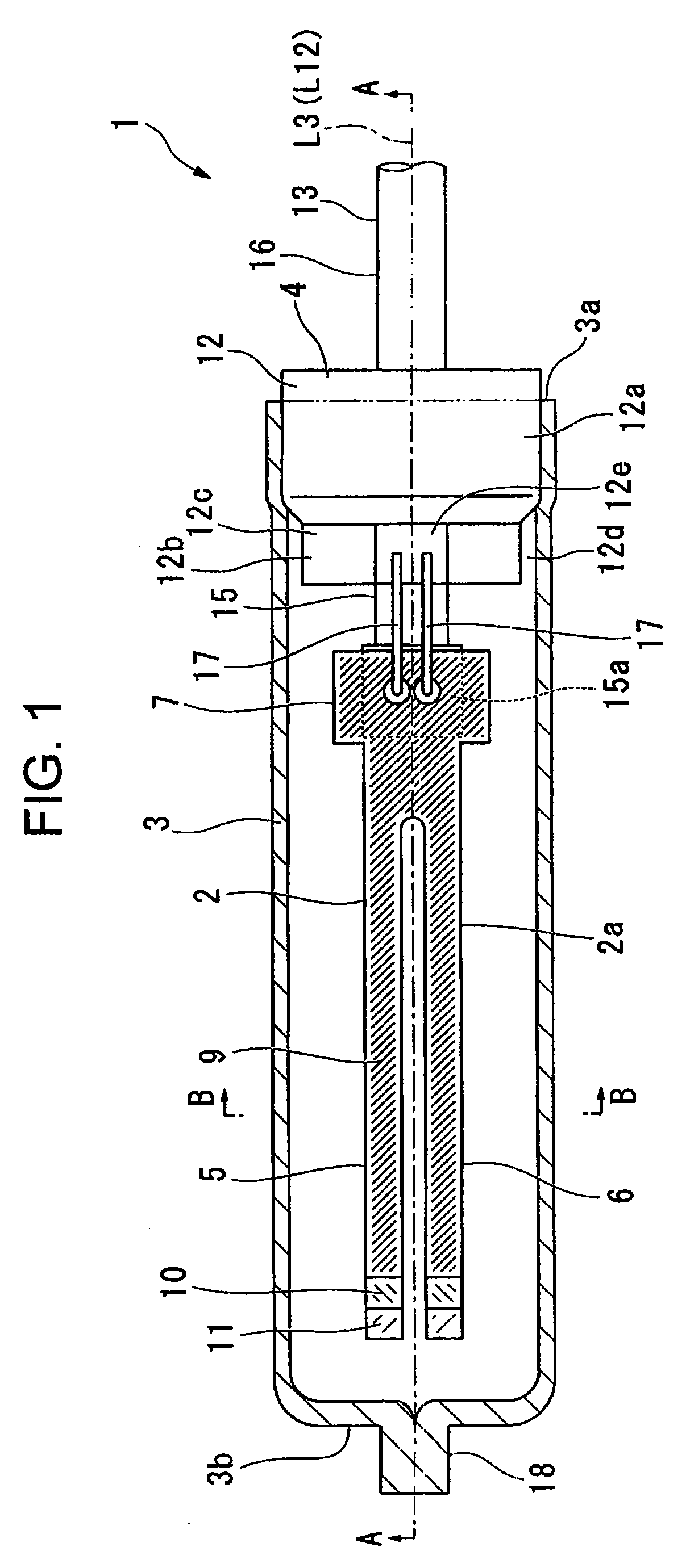
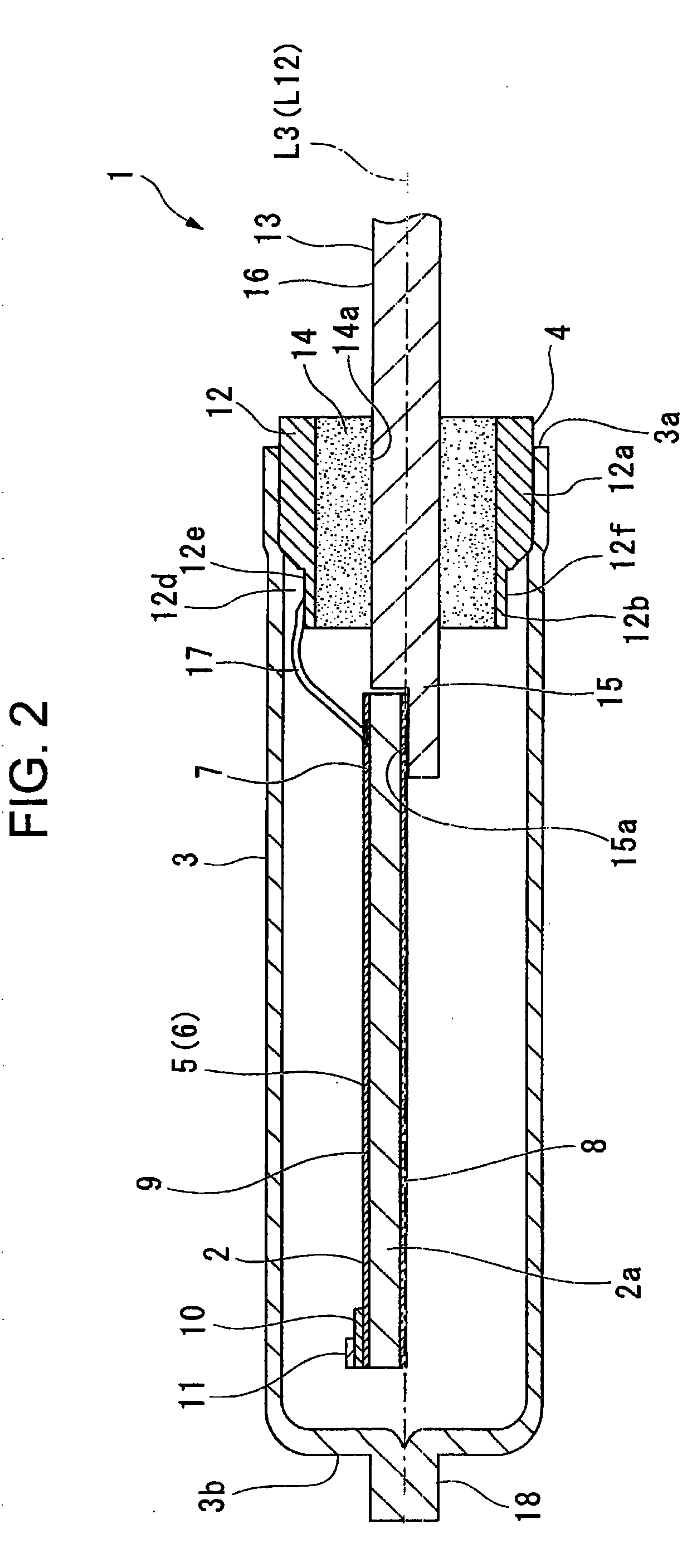
[0065]FIGS. 1 to 3 each show a diagram depicting a piezoelectric oscillator according to a first embodiment of the invention. FIG. 1 shows a cross sectional side view depicting the piezoelectric oscillator according to the embodiment overall, FIG. 2 shows a cross section depicting line A-A shown in FIG. 1, and FIG. 3 shows a cross section depicting line B-B shown in FIG. 1.
[0066]As shown in FIGS. 1 to 3, a piezoelectric oscillator 1 according to the embodiment is a cylinder package piezoelectric oscillator, which is configured to include a piezoelectric vibrating piece 2, a case 3 in a nearly cylindrical shape with a bottom which accommodates the piezoelectric vibrating piece 2 therein and covers therearound, and a hermetic terminal 4 which hermetically seals an opening 3a of the case 3. In the embodiment, the piezoelectric vibrating piece 2 is a tuning fork vibrating piece, which is formed of a quartz crystal piece 2a in a nearly plate shape having a pair of oscillating arm portion...
second embodiment
[0127]FIG. 27 and FIG. 28 each show a second embodiment of the invention. In the embodiment, the members overlapping with the members used in the embodiment described above are designated the same numerals and signs, omitting explanations.
[0128]As shown in FIG. 27 and FIG. 28, this piezoelectric oscillator 50 according to the embodiment is a surface mounted piezoelectric oscillator in which the piezoelectric oscillator 1 according to the first embodiment is resin molded. More specifically, the piezoelectric oscillator 50 includes a case 3, a hermetic terminal 4 which hermetically seals an opening 3a of the case 3, a piezoelectric vibrating piece 2, not shown, arranged inside the case 3, and a resin body 51 which is formed of a resin for covering the case 3, a first outer lead portion 16 and a second outer lead portion 18. To each of the first outer lead portion 16 and the second outer lead portion 18, an external terminal 52 is connected. The external terminal 52 includes a fitting ...
third embodiment
[0130]FIG. 29 shows a third embodiment of the invention. In the embodiment, the members overlapping with the members used in the embodiment described above are designated the same numerals and signs, omitting explanations.
[0131]FIG. 29 shows a schematic diagram depicting the configuration of a tuning fork quartz crystal oscillator according to the invention, showing a plan view depicting a surface mounted piezoelectric oscillator using the piezoelectric oscillator discussed above. As shown in FIG. 29, in this oscillator 100 according to the embodiment, a cylinder package piezoelectric oscillator 1 is configured as an oscillating element electrically connected to an integrated circuit 101. In addition, the piezoelectric oscillator 1 is the same as that of the first embodiment, omitting the explanations. The oscillator 100 has a substrate 103 on which an electronic component 102 such as a condenser is mounted. The substrate 103 is mounted with the integrated circuit 101 for the oscill...
PUM
| Property | Measurement | Unit |
|---|---|---|
| Thickness | aaaaa | aaaaa |
| Diameter | aaaaa | aaaaa |
| Length | aaaaa | aaaaa |
Abstract
Description
Claims
Application Information
 - R&D
- Intellectual Property
- Life Sciences
- Materials
- Tech Scout
- Unparalleled Data Quality
- Higher Quality Content
- 60% Fewer Hallucinations
Browse by: Latest US Patents, China's latest patents, Technical Efficacy Thesaurus, Application Domain, Technology Topic, Popular Technical Reports.
© 2025 PatSnap. All rights reserved.Legal|Privacy policy|Modern Slavery Act Transparency Statement|Sitemap|About US| Contact US: help@patsnap.com


