
Removably Mountable, Portable Vision System

a vision system and portable technology, applied in the field of wireless camera systems, can solve the problems of large monitors, inability to provide drivers with video images, and inability to provide users with mounting flexibility

Inactive Publication Date: 2009-02-12
TWO LOONS TRADING
View PDF11 Cites 43 Cited by
  • Summary
  • Abstract
  • Description
  • Claims
  • Application Information

AI Technical Summary

Benefits of technology

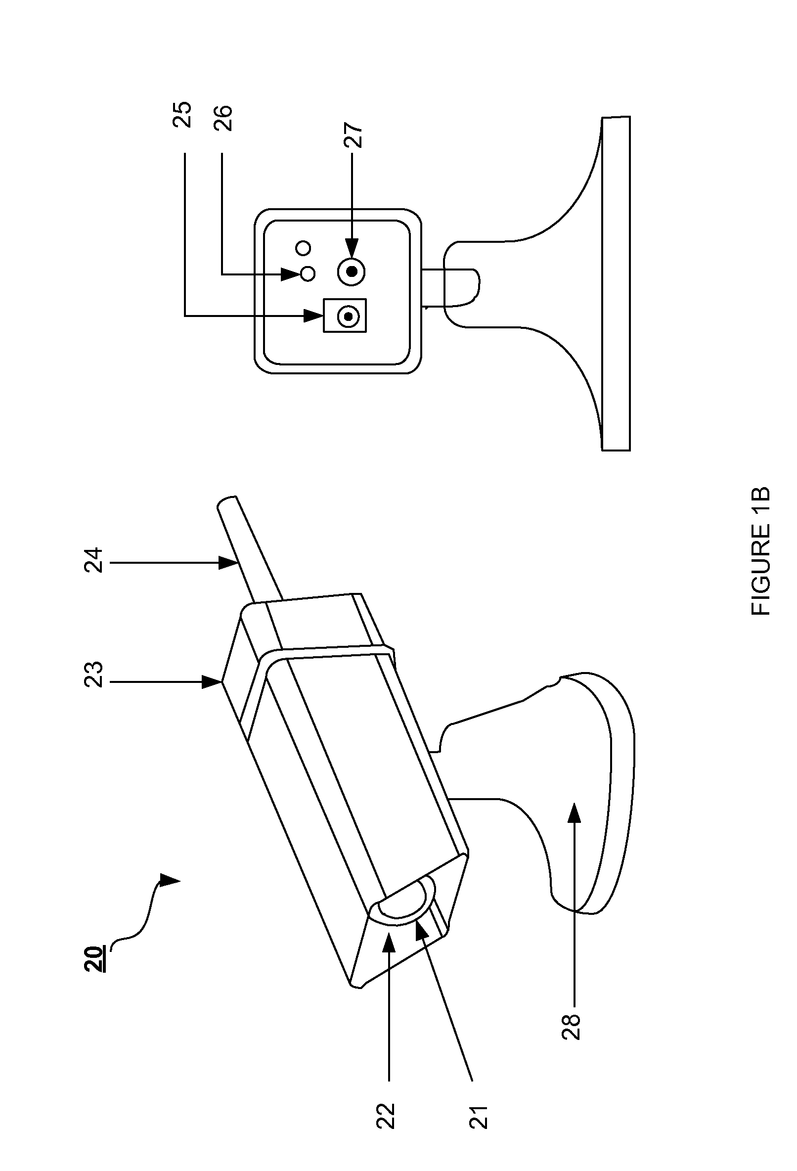
[0008]A removably mountable, portable vision system, the portable vision system including a portable, auto-focusing camera, which is removably mountable to a surface, for capturing and transmitting video to a portable hand-held receiver where the video is displayed as an aid to the user. The system may be used in a variety of vehicle applications, such as attaching a snow plow or backing up and connecting a trailer hitch. The auto-focusing camera provides for quick installation by eliminating manual focusing of the camera by the user. In addition, the system utilizes a single wireless channel for data transmission, eliminating the need for the user to select a wireless channel before use. Finally, the receiver has normal and reverse image display modes of operation, enabling the system to provide the user with an optimal video image regardless of the mounting location of the camera and the current application of the system.

Problems solved by technology

Known portable vision systems that can be used to aid the driver of a vehicle suffer a few disadvantages as they can be large and cumbersome, difficult to set up, and cannot provide the user with mounting flexibility while still providing a video image that makes steering intuitive.
However, the system is unable to provide the driver with a video image that allows for intuitive steering of the vehicle for all possible camera mounting locations.
However, the monitor is large and bulky, and must be plugged in to the vehicle's accessory power plug.
The monitor size and the need for it to be plugged in to operate makes adjusting the field of view of the camera difficult as the user is generally unable to make changes to the camera's position while viewing the camera's field of view on the monitor.
Additionally, the system is unable to provide the driver with a video image that allows for intuitive steering of the vehicle for all possible camera mounting locations
Once again, the system is unable to provide a video image that enables intuitive steering for all camera mounting locations.
These required steps increase the complexity and time spent setting up and troubleshooting the system.

Method used


Image

  • Removably Mountable, Portable Vision System
  • Removably Mountable, Portable Vision System
  • Removably Mountable, Portable Vision System

Examples


Embodiment Construction

[0013]While this invention is illustrated and described in a preferred embodiment, the device may be produced in many different configurations, forms and materials. There is depicted in the drawings, and will herein be described in detail, a preferred embodiment of the invention, with the understanding that the present disclosure is to be considered as an exemplification of the principles of the invention and the associated functional specifications for its construction and is not intended to limit the invention to the embodiment illustrated. Those skilled in the art will envision many other possible variations within the scope of the present invention.

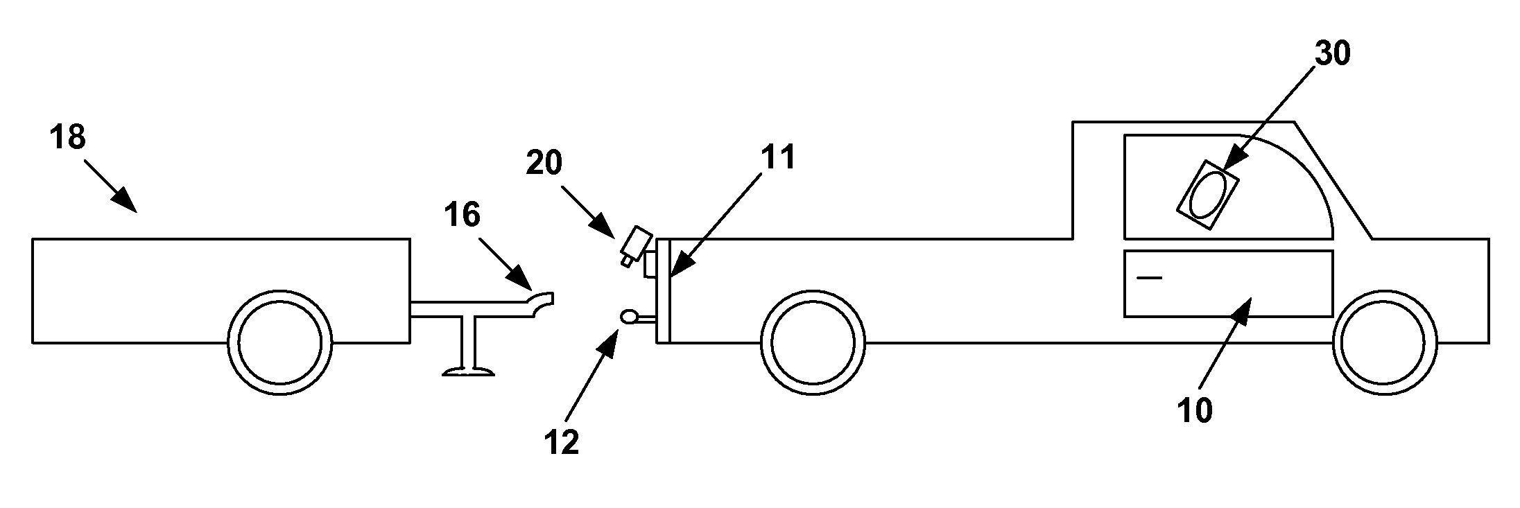
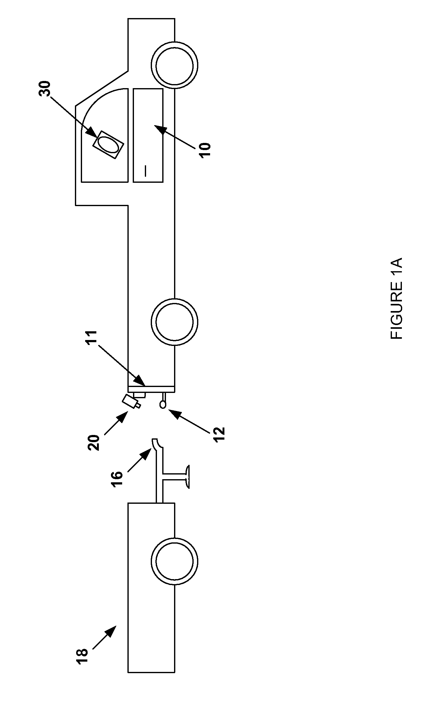
[0014]The removably mountable, portable vision system for aiding a driver of a vehicle in an exemplary embodiment and application is illustrated in FIG. 1A. As shown, the system comprises a camera 20 that is removably mounted to tailgate 11 of vehicle 10. The camera is positioned such that the field of view of the camera images tow hi...


PUM


Abstract

A removably mountable, portable vision system, the portable vision system including a portable, auto-focusing camera, which is removably mountable to a surface, for capturing and transmitting video to a portable hand-held receiver where the video is displayed as an aid to the user. The system may be used in a variety of vehicle applications, such as attaching a snow plow or backing up and connecting a trailer hitch. The auto-focusing camera provides for quick installation by eliminating manual focusing of the camera by the user. In addition, the system utilizes a single wireless channel for data transmission, eliminating the need for the user to select a wireless channel before use. Finally, the receiver has normal and reverse image display modes of operation, enabling the system to provide the user with an optimal video image regardless of the mounting location of the camera and the current application of the system.

Description

BACKGROUND OF THE INVENTION[0001]1. Field of Invention[0002]The present invention relates generally to the field of wireless camera systems. More specifically, the present invention provides a removably mountable, portable vision system, the portable vision system including a portable, auto-focusing camera, which is removably mountable to a surface, for capturing and transmitting video wirelessly to a portable hand-held receiver, the receiver display the received video. Particularly, the system of the present invention will be discussed in the context of applications in which the system is used to aid the driver of a vehicle.[0003]2. Discussion of Prior Art[0004]Known portable vision systems that can be used to aid the driver of a vehicle suffer a few disadvantages as they can be large and cumbersome, difficult to set up, and cannot provide the user with mounting flexibility while still providing a video image that makes steering intuitive. U.S. patent application publication 2003 / 0...

Claims


Application Information

Patent Timeline
Patent Type & Authority Applications(United States)
IPC IPC(8): H04N7/18B60Q1/00H04N5/225H04N5/232
CPCB60R1/00B60R1/003H04N7/185H04N5/23293B60R2300/808H04N23/63H04N23/695
Inventor SCRIBNER, MARK
Owner TWO LOONS TRADING
Learn More