Light Source Reflector

a technology of reflector and light source, which is applied in the field of reflectors, can solve the problems of difficult improvement of light refraction poor light reflection effect of flat reflective surface ab>1/b>, etc., and achieve excellent reflection, poor light refracting and light mixing effect, and improve disadvantages

Inactive Publication Date: 2009-02-12
JENN FENG NEW ENERY CO LTD
View PDF5 Cites 17 Cited by
  • Summary
  • Abstract
  • Description
  • Claims
  • Application Information

AI Technical Summary

Benefits of technology

[0007]The primary objective of the present invention is to improve the disadvantage of the conventional light source reflector that has the poor light-refracting and light-mixing effect.
[0008]Instead of the smooth reflective inner surface of the conventional light source reflector, the present invention provides a plurality of small unit curved surfaces on a conical reflective surface. Each of the unit curved surfaces has a smooth surface as well. As the light beam is emitted to the unit curved surfaces, the light beam can be not only excellently reflected, but also effectively refracted and mixed.
[0009]To achieve above-mentioned objective, a light source reflector in accordance with the present invention is integrally formed by injection molding and includes a conical reflective surface and a flat reflective surface formed on a rim of the conical reflective surface, in which a plurality of unit curved surfaces with a convex surface or a concave surface are formed on the conical reflective surface. A plurality of refraction protrusions are arranged on the flat reflective surface. The conical reflective surface and the flat reflective surface are processed to form a smooth mirror by using electroplating method, to improve the optical efficiency and light-mixing effect of the light source reflector.

Problems solved by technology

However, because the flat reflective surface A1 does not reflect the light beam directly from the light source, the light reflection effect of the flat reflective surface A1 is relatively poor.
Although the above-mentioned conical reflective surface A2 of the conventional light source reflector has a curved mirror surface for providing an excellent reflection function, the light refraction and the light-mixing effect are still hard to be improved.

Method used


Image

  • Light Source Reflector
  • Light Source Reflector
  • Light Source Reflector

Examples


Embodiment Construction

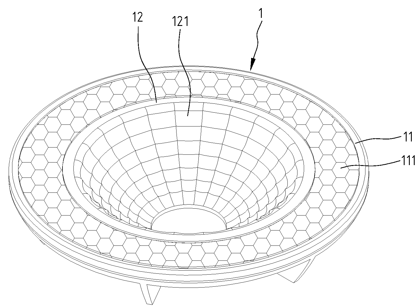
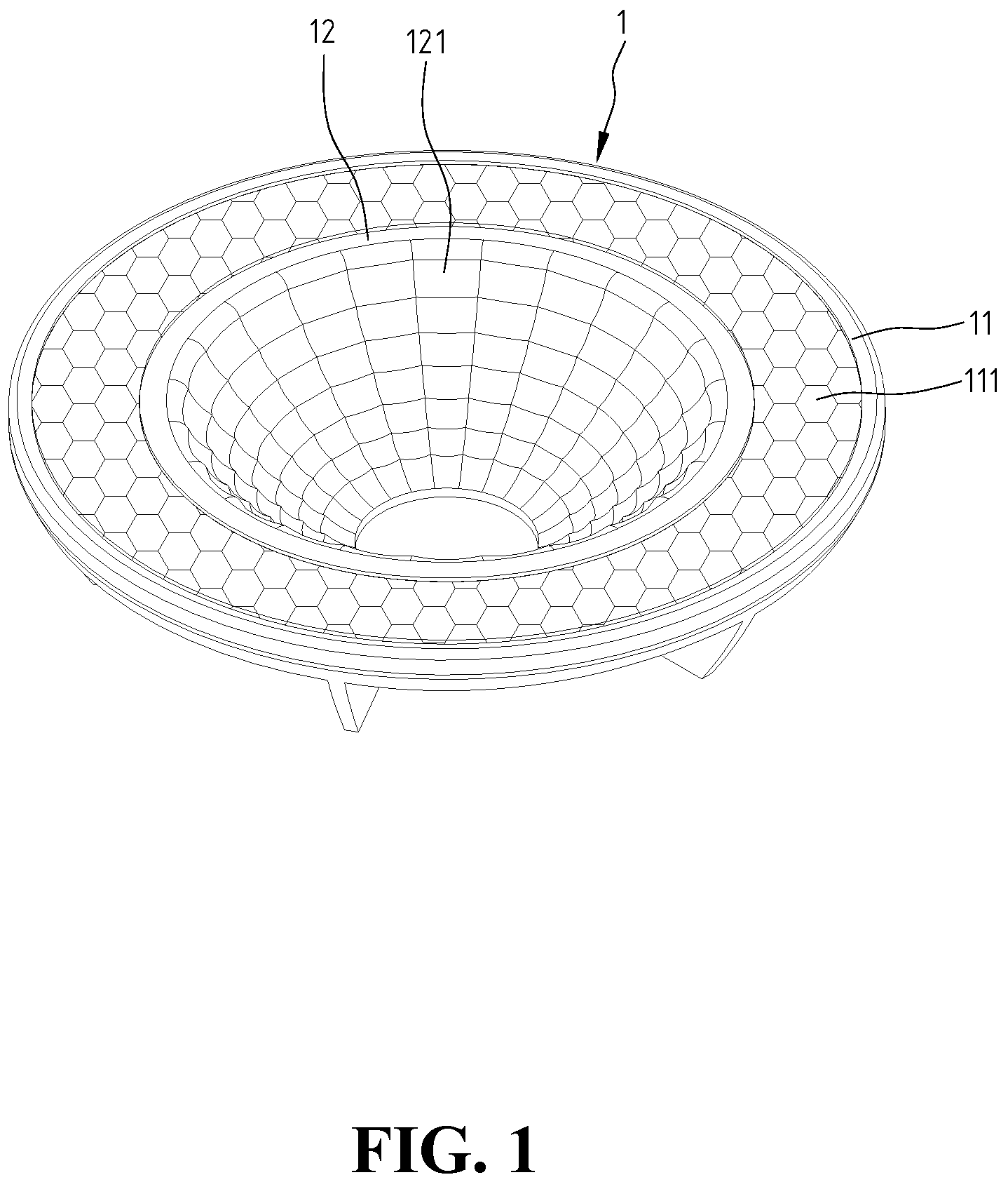
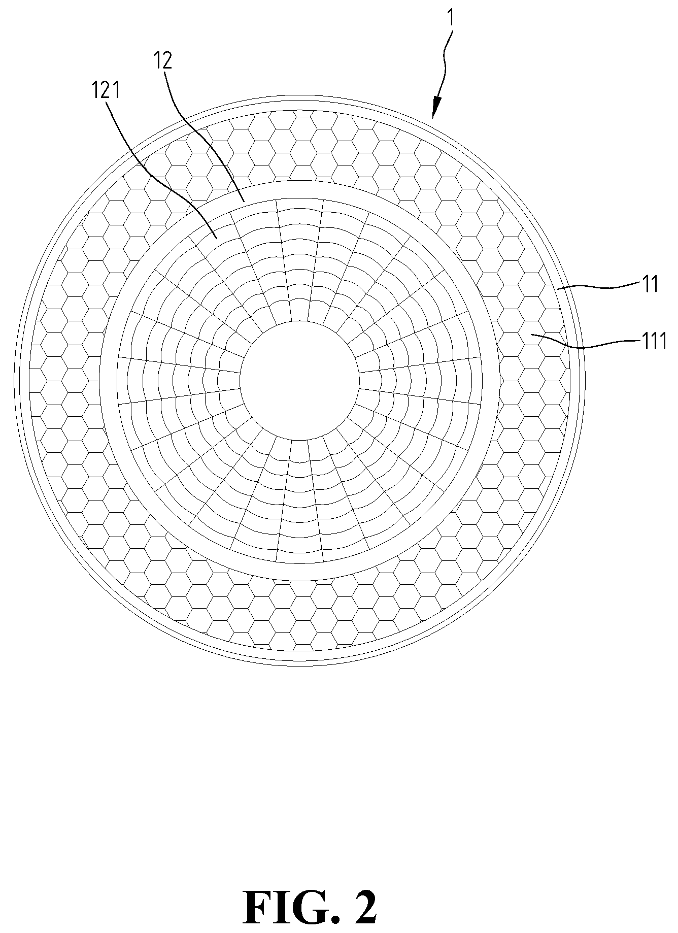
[0015]With reference to FIG. 1 and FIG. 3, a light source reflector 1 in accordance with a preferred embodiment of the present invention is integrally formed by injection molding, and includes a conical reflective surface 12 and a flat reflective surface 11 formed on a rim of the conical reflective surface 12. A plurality of unit curved surfaces 121 with proper sizes are formed on the conical reflective surface 12, in which the unit curved surfaces 121 may have a convex surface protruded from the conical reflective surface or a concave surface recessed in the conical reflective surface, such that the conical reflective surface is configured like a web. Furthermore, a plurality of refraction protrusions 111 are arranged on the flat reflective surface 11. The refraction protrusions 111 have proper size and may be of a pyramid or cone shape. The flat reflective surface 11 and the conical reflective surface 12 can be processed to form a smooth mirror by using electroplating method.

[0016...


PUM


Abstract

A light source reflector includes a conical reflective surface, and a flat reflective surface formed on a rim of the conical reflective surface. The conical reflective surface has a plurality of unit curved surfaces with convex surfaces or concave surfaces. Also, the flat reflective surface is provided with a plurality of refraction protrusions, to improve the optical efficiency and light-mixing effect of the light source reflector.

Description

BACKGROUND OF THE INVENTION[0001]1. Field of the Invention[0002]The present invention relates to a reflector mounted with a light source, such as a light-emitting diode or a bulb, for reflecting the light beam emitted from the light source.[0003]2. The Prior Arts[0004]Generally, lamp devices for illumination purpose are assembled with a light source reflector to increase the light brightness.[0005]With reference to FIG. 4, a conventional light source reflector A, which is integrally formed by injection molding, includes a conical reflective surface A2, and a flat reflective surface A1 formed on a rim of the conical reflective surface A2. An insertion hole is provided at a center of the conical reflective surface A2, through which a light source, such as a light-emitting diode or a bulb, can be inserted. When the light source disposed at the center of the conical reflective surface A2 is turned on, part of the light beam emits off the light source reflector A directly, and part of th...

Claims


Application Information

Patent Timeline
Patent Type & Authority Applications(United States)
IPC IPC(8): F21V13/04F21V7/04
CPCF21V7/041F21V7/048F21Y2101/02F21V13/04F21V7/09F21Y2101/00F21Y2115/10
Inventor LO, KANG HUA
Owner JENN FENG NEW ENERY CO LTD
Why Eureka
Try Eureka