Emergency Communications System

a communication system and emergency technology, applied in the field of emergency communication systems, can solve the problems of emergency responders having no direct radio communication with personnel located, emergency situation turning into a tragedy, and difficult for organizational personnel to directly speak with responders prior to emergency situation, etc., to achieve high speed, activate and deactivate the bridge

Active Publication Date: 2009-02-12
SAFECOM 911
View PDF44 Cites 46 Cited by
  • Summary
  • Abstract
  • Description
  • Claims
  • Application Information

AI Technical Summary

Benefits of technology

[0008]In accordance with the present invention, a communication system and method is provided for handling emergency situations wherein complex public safety radio systems can be used to directly communicate with normally incompatible radio systems used by organizations such as schools, hospitals, and other large independent facilities. The system of the present invention includes a radio communication patch or bridge that is selectively activated by emergency personnel to contact one or more selected organizations. In a preferred embodiment of the present invention, the communication system further includes a communication network, such as a local area network (LAN) or a group of LANs and a high speed interconnecting network such as the Internet. Activation and deactivation of the bridge is achieved over the LAN(s). A computer server may be located at one of several locations such as at a 911 call center, school district headquarters, or school district security center. This server is used to monitor and control the emergency communication system with one or more communication endpoints that are linked to the server. Each of the communication endpoints, such as separate schools, each have an IP address that allows them to be connected over the network(s) by the server. Each of the communication endpoints also has their own local two-way radio system and a communication patch or bridge device that is activated or enabled by IP commands over the network(s). Activation of the bridge is typically prompted by a 911 call by the affected organization at the communication end point. The 911-call center then evaluates the particular emergency, and can selectively activate over the network(s) the radio bridge. Once the bridge is activated, personnel located at the communication end point can then directly communicate with the emergency responders who have been dispatched and who are operating their radios on the public safety radio system. The local radios at the communication endpoints operate on their normal frequency / channel and once the bridge is activated then the local radios are automatically merged with the public safety radio channel or talk group. When the bridge is deactivated, the radios cease to operate on the public safety radio frequency / channel and are automatically returned to their normal channel operation.

Problems solved by technology

However, emergency responders have no direct means of radio communication with personnel located at the emergency location.
Regardless of the nature of the incident and the identity of the emergency responders, it is very difficult for organizational personnel to directly speak with the responders prior to the responders arriving at the location.
Many emergency situations are time critical and the ability for organizational personnel to provide instantaneous information as to the status of the emergency can make the difference between emergency responders properly handling the situation as opposed to such responders not having adequate information, and the emergency situation then turning into a tragedy.
Because of the necessity to ensure that emergency responders have the ability to communicate with one another, Federal regulations limit the types of organizations that may operate on the same frequency bands as emergency personnel.
As mentioned above with respect to organizations who use two-way radio systems for daily operations, these radio systems are not able to communicate with emergency radio systems since each operate on very distinct frequencies, and the nature of the RF signals produced during the communications are very different.
Therefore, other than the 911 telecommunications, affected personnel at the organization cannot communicate with emergency responders until they arrive at the scene.

Method used


Image

  • Emergency Communications System
  • Emergency Communications System
  • Emergency Communications System

Examples


Embodiment Construction

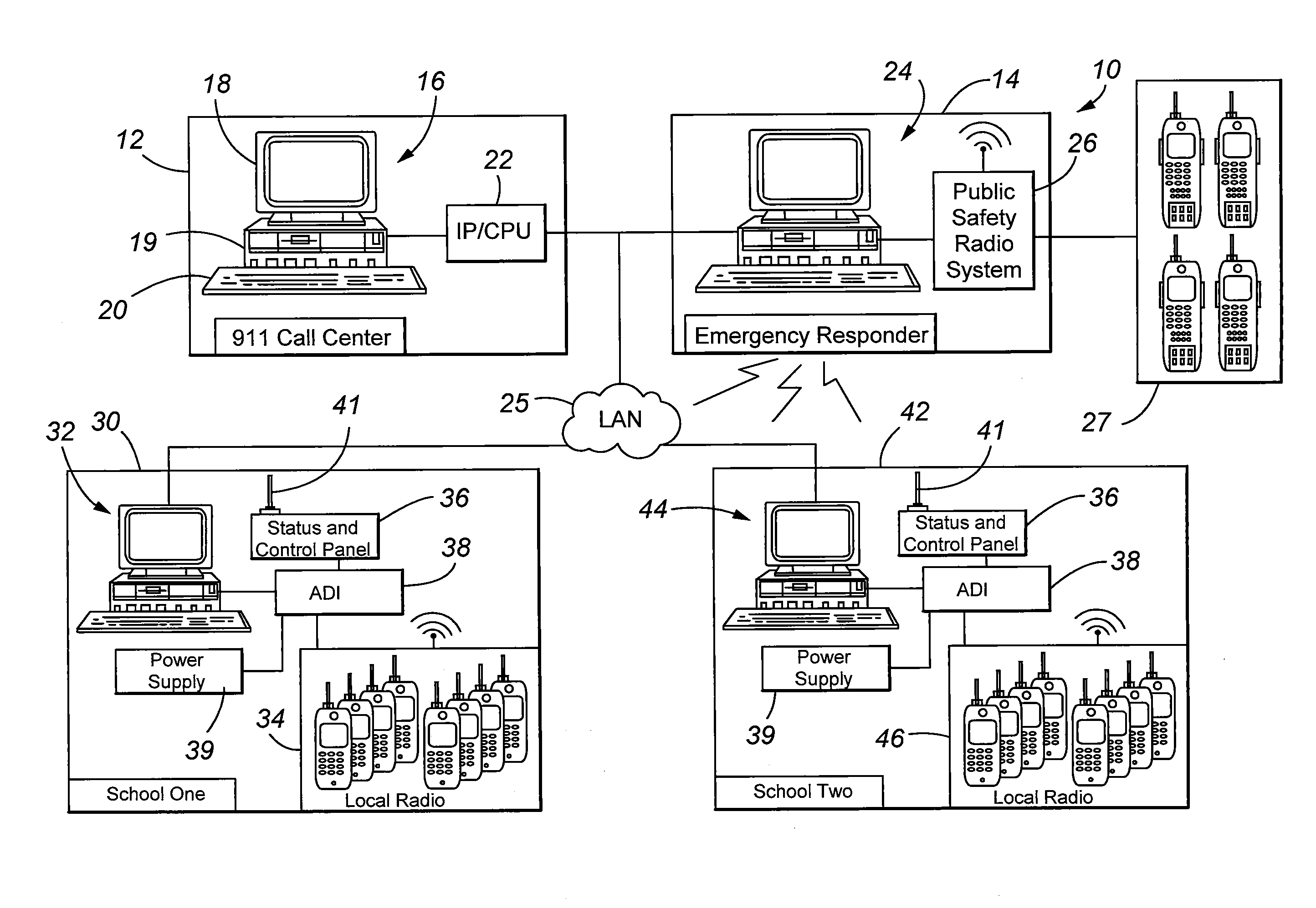
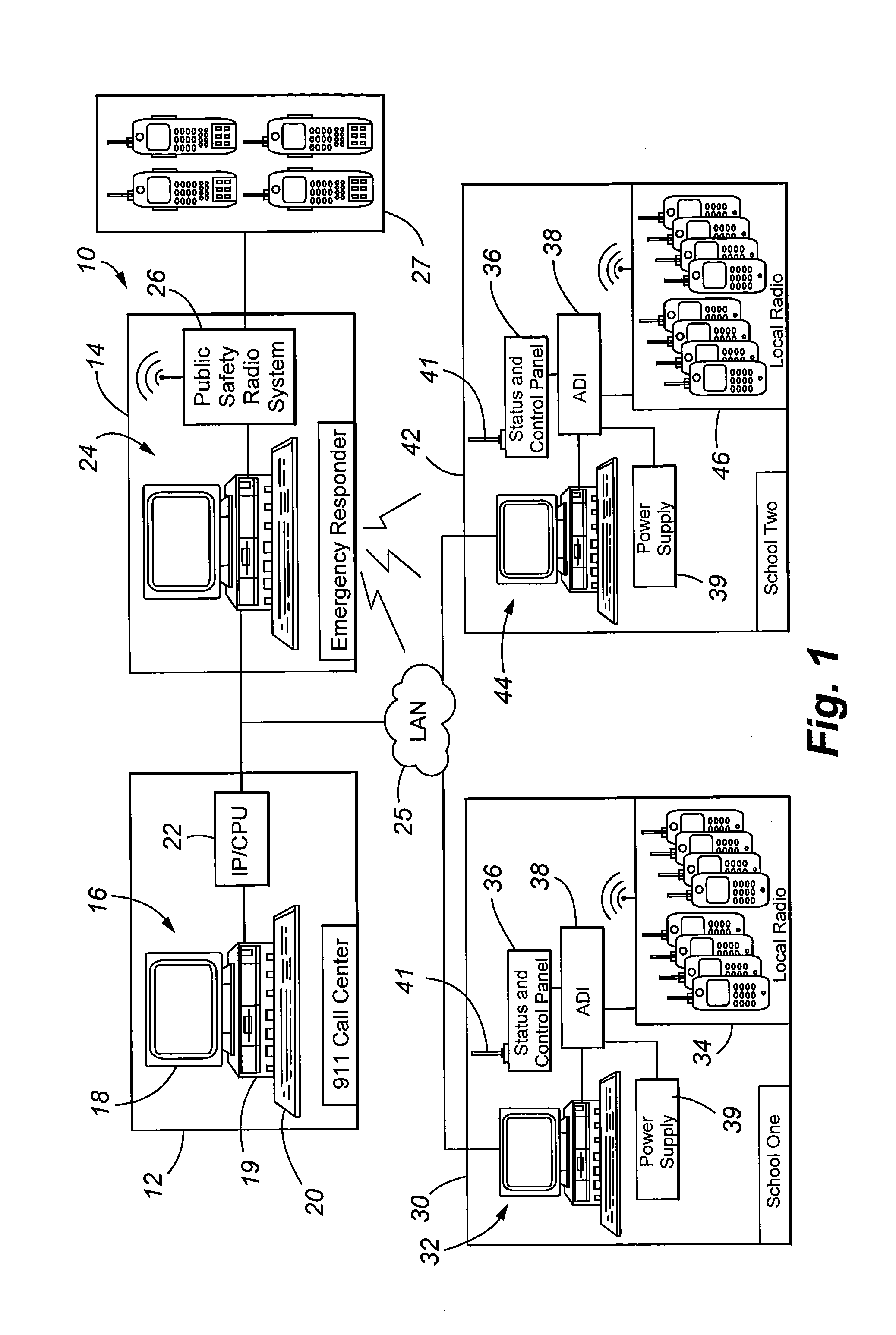
[0029]Referring first to FIG. 1, the communication system 10 of the present invention is illustrated. A 911 call center 12 is equipped with one or more computer processing units 16 which are able to administer 911 calls coming into the center and appropriately assigning actions to be taken by emergency responders located at responder location 14. A 911 call center computer / server 16 is shown as being conventional with a user interface such as a screen or monitor 18, a computer processor or server 19, and one or more input devices 20 such as a keyboard or a mouse. A separate Internet protocol / central processing unit (CPU) 22 is illustrated as being co-located within the 911-call center. This particular CPU 22 has computer-coded instructions in the form of firmware or software that facilitates the functionality of the present invention, as further discussed below. This CPU 22 may also be defined as a computer server with a connection to at least one local area network and the Internet...


PUM


Abstract

A communication system and method is provided for handling emergency situations wherein complex public safety radio systems can be used to directly communicate with normally incompatible radio systems used by organizations such as schools, hospital, and other facilities. The system includes a radio communication bridge that is selectively activated by emergency personnel to contact selected organizations. The bridge is activated via a TCP/IP command sent from an organization having activation privileges to the selected communication endpoints. Computer software or firmware installed at various communication endpoints, emergency responder locations, and at an emergency call center is used to facilitate functionality of the system to include emergency notifications, dissemination of information associated with a particular emergency, and the status of the system to include activation and deactivation of the radio bridge.

Description

CROSS REFERENCE TO RELATED APPLICATION[0001]This application is a continuation-in-part of application Ser. No. 11 / 682,231 filed on Mar. 5, 2007, entitled “Emergency Communications System”, the entire disclosure of which is hereby incorporated by reference.FIELD OF THE INVENTION[0002]The present invention relates to communication systems incorporating multiple communication modes, and more particularly, to an emergency communication system for bridging incompatible radio communication elements.BACKGROUND OF THE INVENTION[0003]Many organizations have internal radio systems to manage day-to-day operations to include organization security. Various staff or security personnel may be equipped with radios enabling basic two-way communications between personnel. For many years, emergency or first responders such as law enforcement and fire departments have used radios for communications.[0004]Because of the required range and necessity for reliability, government officials communicating by ...

Claims


Application Information

Patent Timeline
Patent Type & Authority Applications(United States)
IPC IPC(8): H04M11/04H04B7/00
CPCH04W76/007H04W4/22H04W4/90H04W76/50
Inventor HOBBY, PATRICK L.PETTY, DAVID E.
Owner SAFECOM 911
Why Eureka
Try Eureka