Speaker diaphragm and electrodynamic loudspeaker using the same

a loudspeaker and diaphragm technology, applied in the direction of transducer diaphragms, electromechanical transducers, instruments, etc., can solve the problems of difficult to obtain a flat frequency response, difficult to set the highest reproducible frequency to be high, and difficult to achieve flat frequency response, etc., to achieve desirable sound reproduction quality, improve symmetry, and increase the rigidity of the elongated loudspeaker diaphragm

Inactive Publication Date: 2009-02-12
ONKYO KK
View PDF5 Cites 14 Cited by
  • Summary
  • Abstract
  • Description
  • Claims
  • Application Information

AI Technical Summary

Benefits of technology

[0022]For example, the major-axis central rib of the reinforcement rib may be a rib that extends continuously through one of the second diaphragm portions, the first diaphragm portion and the other second diaphragm portion. Alternatively, the major-axis central rib may be divided into two separate ribs, including a first major-axis central rib and a second major-axis central rib, which are arranged with the junction to the voice coil bobbin being interposed therebetween, with the height of the ribs being largest in the first diaphragm portion and gradually decreasing through the second diaphragm portion toward either end in the major-axis direction. The reinforcement rib, including the major-axis central rib, enables the reproduction of the middle and high ranges in the first diaphragm portion as will be described below, and also ensures the symmetry between the forward and backward amplitudes, while increasing the rigidity of the elongated loudspeaker diaphragm in the major-axis direction.
[0023]The edge with a non-uniform thickness includes a free edge portion for freely supporting the opposite ends of the first diaphragm portion and the second diaphragm portions in the minor-axis direction, and a fixed edge portion being thicker than the free edge portion for fixedly supporting the distal end of each second diaphragm portion in the major-axis direction. The opposite ends of the diaphragm body of the present invention in the minor-axis direction (i.e., portions corresponding to the long sides of the diaphragm body) are freely supported by the free edge portion of the edge, and the opposite ends thereof in the major-axis direction (i.e., portions corresponding to the short sides of the diaphragm body) are fixedly supported by the fixed edge portion of the edge. Therefore, where the elongated loudspeaker diaphragm has the major axis significantly longer than the short axis and where the voice coil substantially displaces at a frequency near or below the lowest resonance frequency f0, the loudspeaker diaphragm vibrates in a lowest-order bending vibration mode where the opposite ends in the major-axis direction are fixedly supported to become the nodes while the central portion in the major-axis direction becomes the antinode, whereby it is possible to realize a flat frequency response while suppressing dips which are likely to first appear in the low range. Moreover, due to the rigidity of the reinforcement rib, it is possible to improve the symmetry between the forward and backward amplitudes of the loudspeaker diaphragm, thereby realizing an electrodynamic loudspeaker having a desirable sound reproduction quality with little distortion.
[0024]Moreover, the first diaphragm portion of the diaphragm body has an area larger than the projected area of the voice coil bobbin, and the average thickness of the first diaphragm portion is smaller than that of the second diaphragm portion. Thus, since the average thickness of the first diaphragm portion, with the

Problems solved by technology

Particularly, electrodynamic loudspeakers of an elongated shape (e.g., a rectangular shape and an elongated circular shape (including an elliptical shape and a racetrack shape)) have disadvantages in the sound reproducing capability for various reasons, such as: the diaphragm area is limited in the minor-axis direction; there is a significant influence of divided vibrations that are characteristic of a loudspeaker diaphragm of an elongated shape, whereby it is difficult to obtain a flat frequency response; and when a foam resin material, or the like, is employed in order to achieve both a high rigidity and a light weight of the loudspeaker diaphragm, it will not be possible to set the

Method used


Image

  • Speaker diaphragm and electrodynamic loudspeaker using the same
  • Speaker diaphragm and electrodynamic loudspeaker using the same
  • Speaker diaphragm and electrodynamic loudspeaker using the same

Examples


embodiment 1

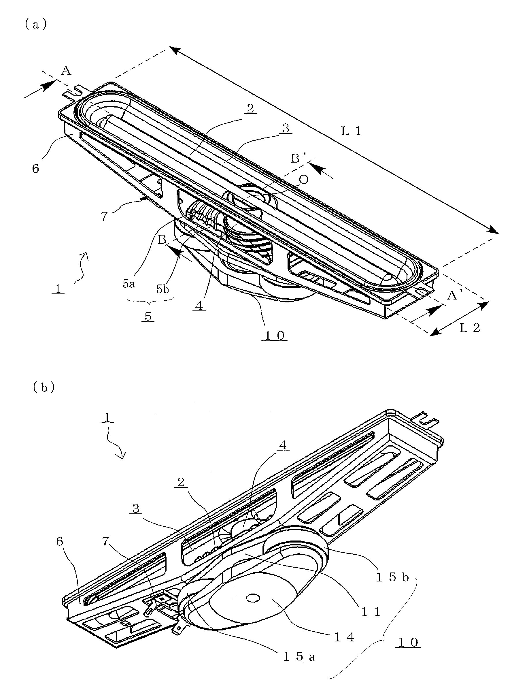
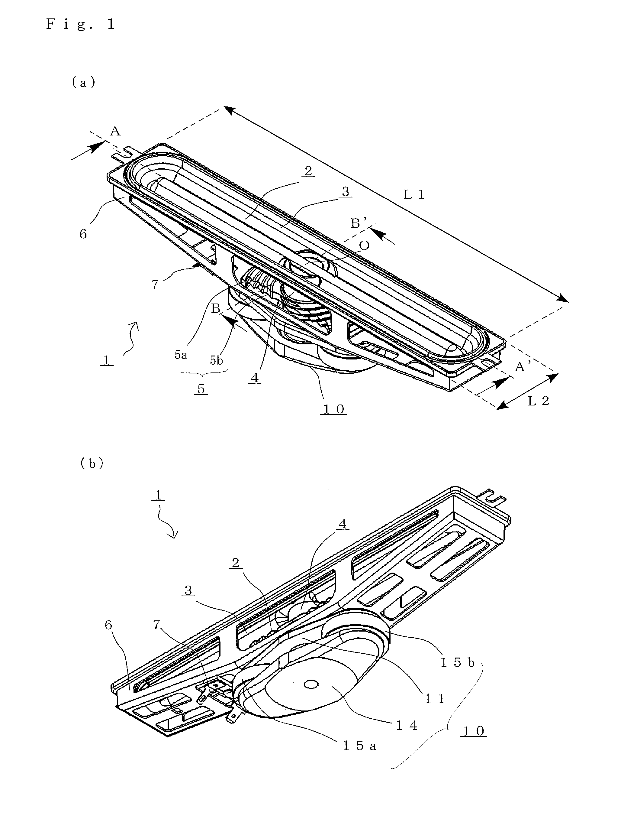
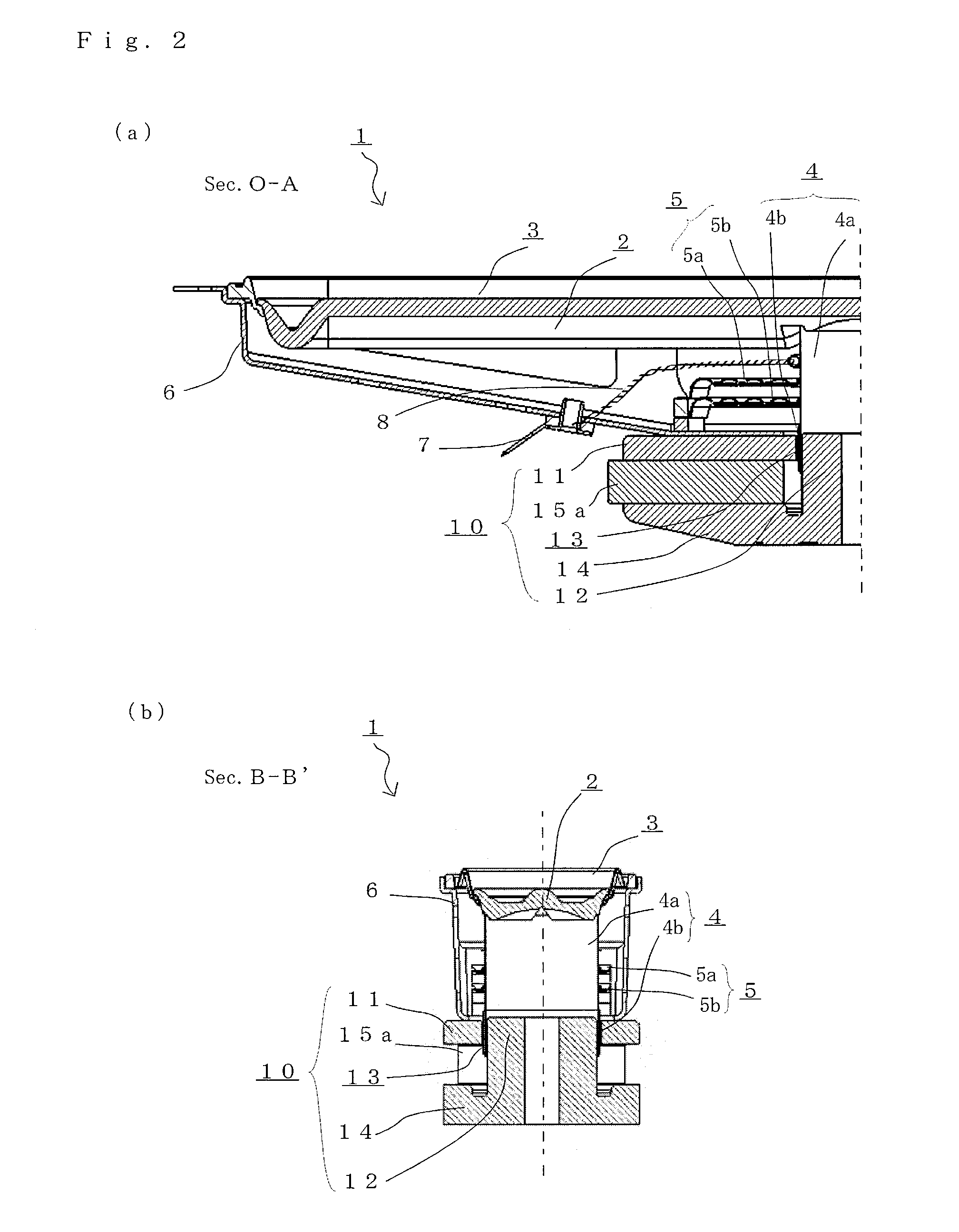
[0038]FIGS. 1A to 2B illustrate an electrodynamic loudspeaker 1 in a preferred embodiment of the present invention. FIG. 1A is a perspective view of the electrodynamic loudspeaker 1 as viewed in an inclined direction from the front side, and FIG. 1B is a perspective view thereof as viewed in an inclined direction from the rear side. FIG. 2A is a cross-sectional view of the electrodynamic loudspeaker 1 taken along line O-A, and FIG. 2B is a cross-sectional view thereof taken along line B-B′. As will be explained later, some elements of the electrodynamic loudspeaker 1, the inner structure thereof, etc., may not be shown in the figures. The direction of line A-A′ is the major-axis direction, and the direction of line B-B′ is the minor-axis direction.

[0039]The electrodynamic loudspeaker 1 of the present embodiment has an elongated shape and includes a racetrack-shaped loudspeaker diaphragm 2 whose length L1 in the major-axis direction is about 210 mm and whose length L2 in the minor-ax...

embodiment 2

[0066]A loudspeaker diaphragm 2A of the present embodiment (not shown) will now be described. The loudspeaker diaphragm 2A is obtained by simultaneously and integrally molding a body portion of the loudspeaker diaphragm 2A, an edge 3A and a reinforcement 34A by using a material obtained by laminating a thermoplastic resin film on the front and rear surfaces of a thermoplastic foam sheet. In the loudspeaker diaphragm 2A, a polyurethane elastomer film is thermally bonded on the front and rear surfaces of an extruded polystyrene paper, which is subjected to a plug-assist vacuum molding as described above to thereby obtain a diaphragm body having the same shape as that of the loudspeaker diaphragm 2 of Embodiment 1 above. The present embodiment differs from Embodiment 1 in that the edge 3A is integrally formed from the polyurethane elastomer film which is extended from the front and rear surfaces of the loudspeaker diaphragm 2A so as to form a free edge at each end in the minor-axis dir...

embodiment 3

[0072]An electrodynamic loudspeaker 1B including a loudspeaker diaphragm 2B (not shown) and an edge 3B (not shown) of the present embodiment will now be described. The loudspeaker diaphragm 2B is the same as the loudspeaker diaphragm 2A of Embodiment 2 above in that a polyurethane elastomer film is thermally bonded on the front and rear surfaces of an extruded polystyrene paper, and will not be further described below. Moreover, the dimensions and the shape of the edge 3B are the same as those of the preceding embodiment. However, the material and the arrangement of the edge 3B are different from those of the preceding embodiment.

[0073]With the edge 3B of the present embodiment, different materials are used, between a first diaphragm portion 21B and a second diaphragm portion 22B, for the free edge portions for freely supporting the opposite ends of the loudspeaker diaphragm 2B in the minor-axis direction along the long sides of the racetrack shape extending in straight lines in the...


PUM


Abstract

The present invention provides a loudspeaker diaphragm and an electrodynamic loudspeaker of an elongated shape being shorter in the minor-axis direction than in the major-axis direction, which have a desirable sound reproducing capability with a high efficiency and are not significantly influenced by divided vibrations of an elongated loudspeaker diaphragm, and which are suitably installed in devices such as display devices. In the elongated loudspeaker diaphragm: the diaphragm body includes a first diaphragm portion in a central portion of a rear surface thereof, the first diaphragm portion including a junction to a voice coil bobbin, a second diaphragm portion extending on each side of the first diaphragm portion in the major-axis direction, and a reinforcement rib extending continuously through the first diaphragm portion and the second diaphragm portions; and the edge includes a free edge portion for freely supporting opposite ends in the minor-axis direction of the first diaphragm portion and the second diaphragm portion, and a fixed edge portion being thicker than the free edge portion for fixedly supporting a distal end of each second diaphragm portion in the major-axis direction.

Description

BACKGROUND OF THE INVENTION[0001]1. Field of the Invention[0002]The present invention relates to a loudspeaker diaphragm and an electrodynamic loudspeaker, and more particularly to those of an elongated shape being shorter in the minor-axis direction than in the major-axis direction (e.g., a rectangular shape and an elongated circular shape (including an elliptical shape and a racetrack shape)), which have a desirable sound reproducing capability and are not significantly influenced by divided vibrations of an elongated loudspeaker diaphragm, and which are suitably installed in devices such as display devices.[0003]2. Description of the Related Art[0004]With an acoustic device, such as a display device, in which a loudspeaker is installed for reproducing sound, there is a demand for reducing the amount of space required for installing the loudspeaker. Particularly, electrodynamic loudspeakers of an elongated shape (e.g., a rectangular shape and an elongated circular shape (including...

Claims


Application Information

Patent Timeline
IPC IPC(8): H04R9/06H04R7/00H04R11/02
CPCH04R7/04H04R2307/025H04R9/06H04R7/18
Inventor TOYOFUKU, KENICHIROKUMO, HIROYASUOKADA, TAIHEI
Owner ONKYO KK
Why Eureka
Try Eureka