Method for Accessing Optical Fibers within a Telecommunication Cable

Inactive Publication Date: 2009-02-12
DRAKA COMTEQ BV
View PDF7 Cites 56 Cited by
  • Summary
  • Abstract
  • Description
  • Claims
  • Application Information

AI Technical Summary

Benefits of technology

[0025]In yet another exemplary embodiment, the pushing-and-cutting is a mechanical milling cutter with a conical or rectangular profile. The tool may be calibrated

Problems solved by technology

The methods and tools described in the aforementioned patent documents, however, do not provide any particular step for protecting the optical fibers or micromodules during the cutting of the bypass insertion windows.
In particular, when the filling rate of the central core (i.e

Method used


Image

  • Method for Accessing Optical Fibers within a Telecommunication Cable
  • Method for Accessing Optical Fibers within a Telecommunication Cable
  • Method for Accessing Optical Fibers within a Telecommunication Cable

Examples


first embodiment

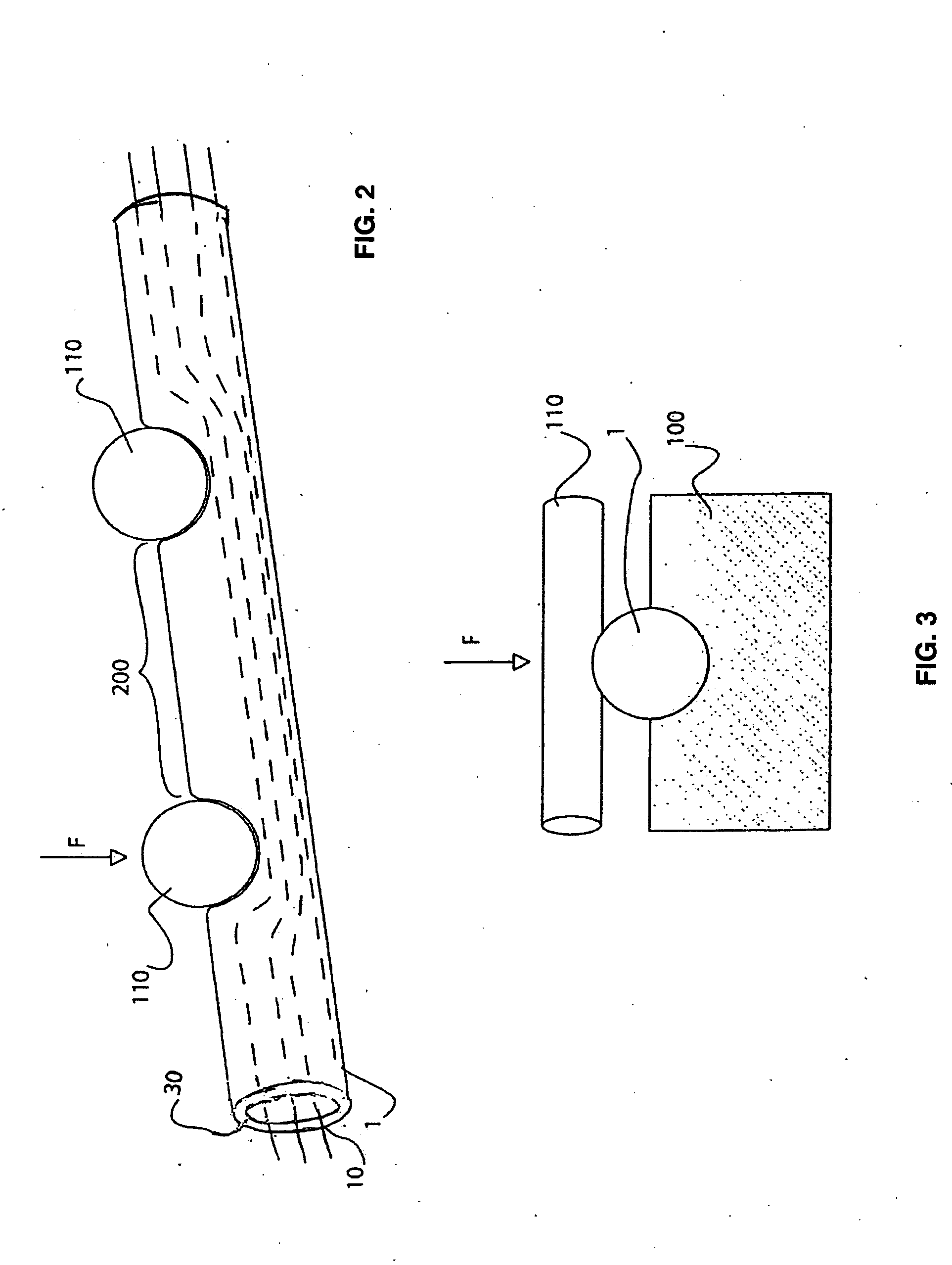
[0055]According to this first embodiment, the micromodules 10 positioned in the cable 1 are pushed away toward a half-section of the central core 20 (i.e., the half-section opposite to the cutout area 200). The micromodules 10 are pushed away by applying a radial force F at two points of the outer periphery of the jacket 30. These two points of applied radial forces F typically lie on either side of the cutout area 200. The radial forces F may be exerted, for example, by two metal rods 110.

[0056]To facilitate this procedure, a jig 100 having the shape of the cable 1 may be placed under the cable 1. The jig 100 is located on the opposite side of the cable 1 with respect to the rods 110 in order to avoid bending the cable 1 or causing the cable 1 to become out-of-round under the effect of the radial forces F. Each radial force F causes a localized deformation of the jacket 30 of the cable 1. These localized deformations penetrate toward the inside of the longitudinal central core 20 o...

third embodiment

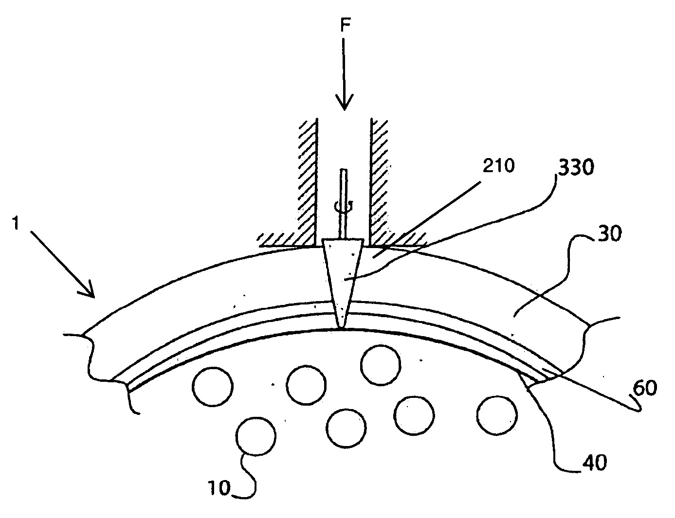
[0062]According to this third embodiment, the pushing tool 310 includes a system of connected members (i.e., legs) that are respectively slid through the insertion windows 210 made in the jacket 30 of the cable 1. These pushing-tool legs are suitable for exerting a radial force F directly on the micromodules 10 (i.e., at two points within the cable 1 corresponding to the cutout area 200).

[0063]For example, the legs of the pushing tool 310 may have an L-shape. A radial force F may be applied to a bar that connects the legs together. A component of this radial force F is thus transmitted to each leg of the pushing tool 310 in order to push the micromodules 10 from the cutout area 200. After the micromodules 10 have been pushed away, an access window may be opened on the cutout area 200 between the two insertion windows 210 using a cutting tool. As before, this procedure considerably reduces the risk of damaging the micromodules 10 with the cutting tool.

[0064]According to a fourth exem...


PUM


Abstract

Disclosed is a method accessing one or more optical fibers in a telecommunication cable in a way that considerably reduces the risk of damaging the optical fibers. To avoid inadvertent damage caused by a cutting tool, the method includes moving optical fibers and/or micromodules away from the area on the cable that is to be cut.

Description

CROSS-REFERENCE TO PRIORITY APPLICATION[0001]This application claims the benefit of pending French Application No. 07 / 02624 (filed Apr. 11, 2007, at the French Patent Office) via 35 U.S.C. §119. French Application No. 07 / 02624 is hereby incorporated by reference in its entirety.FIELD OF THE INVENTION[0002]The present invention relates to the field of optical fiber telecommunication cables and, more particularly, to so-called micromodule cables in which optical fibers are grouped to form a plurality of micromodules gathered together as a cable.BACKGROUND OF THE INVENTION[0003]Optical fiber cables that include several optical fiber micromodules are known. For example, French Patent Application No. FR 2,665,266 and its counterpart U.S. Pat. No. 5,155,789, which is hereby incorporated by reference in its entirety, and French Patent Application No. FR 2,706,218, and its counterpart U.S. Pat. No. 5,671,312, which is hereby incorporated by reference in its entirety, disclose an optical fib...

Claims


Application Information

Patent Timeline
IPC IPC(8): G02B6/44
CPCG02B6/4497G02B6/4495G02B6/566G02B6/4431
Inventor LAVENNE, ALAINTATAT, OLIVIERBONICEL, JEAN-PIERRE
Owner DRAKA COMTEQ BV
Why Eureka
Try Eureka