Method and apparatus for capacity on demand dynamic chunk allocation

a dynamic chunk and capacity technology, applied in the field of storage resource management, can solve the problems of write command failure, conventional storage resource management techniques fail to enable provision of extra capacity (adding new chunks) with short latency

Inactive Publication Date: 2009-02-12
HITACHI LTD
View PDF7 Cites 24 Cited by
  • Summary
  • Abstract
  • Description
  • Claims
  • Application Information

AI Technical Summary

Benefits of technology

[0008]The inventive methodology is directed to methods and systems that substantially obviate one or more of the above and other problems associated with conventional techniques for storage resource management.

Problems solved by technology

If the chunk pool has no chunks available, the write command fails.
However, the conventional storage resource management techniques fail to enable provision of extra capacity (adding new chunks) with short latency by applying the storage-on-demand steps for storage devices with dynamic chunk allocation capability.

Method used


Image

  • Method and apparatus for capacity on demand dynamic chunk allocation
  • Method and apparatus for capacity on demand dynamic chunk allocation
  • Method and apparatus for capacity on demand dynamic chunk allocation

Examples


first embodiment

tion

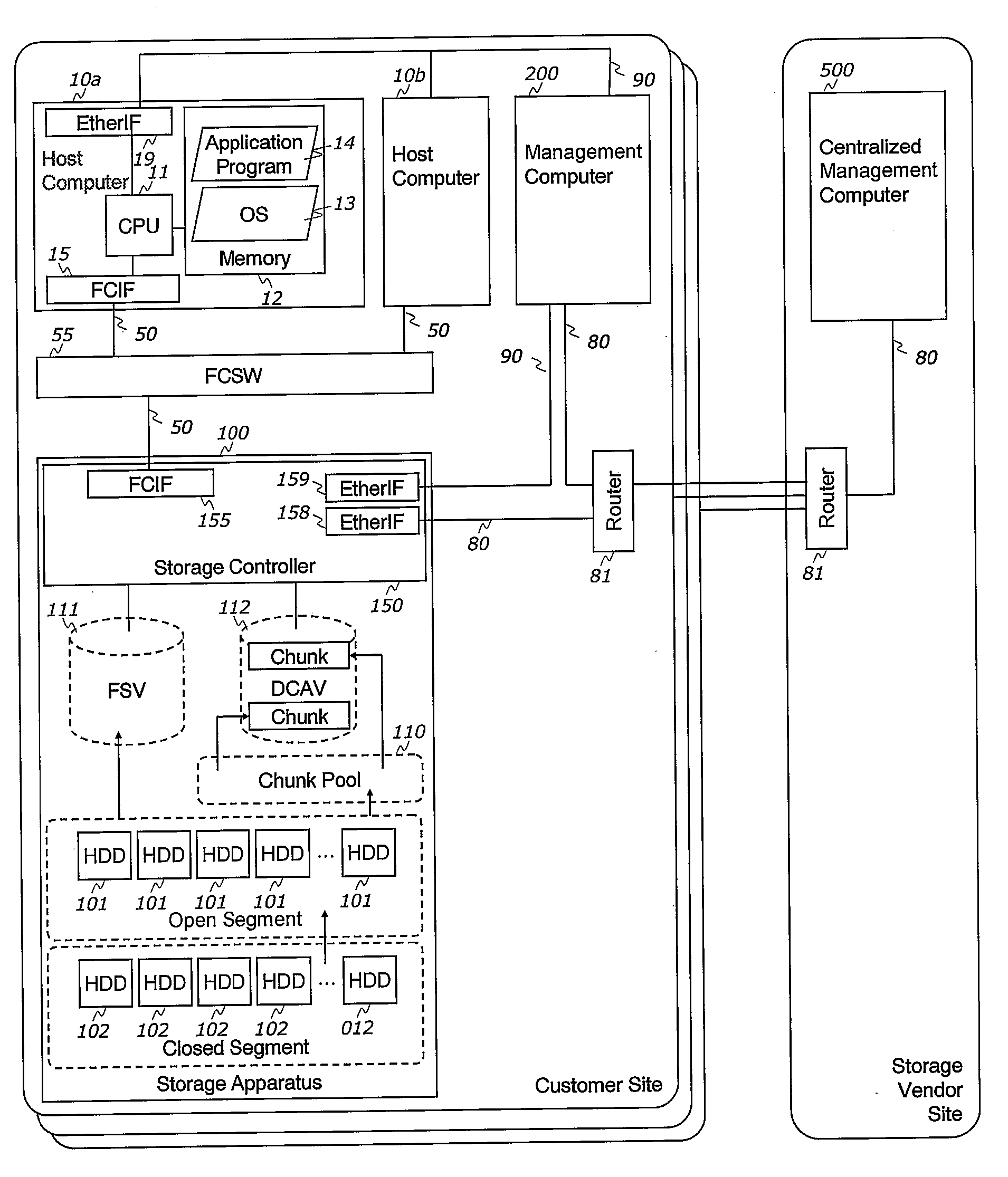
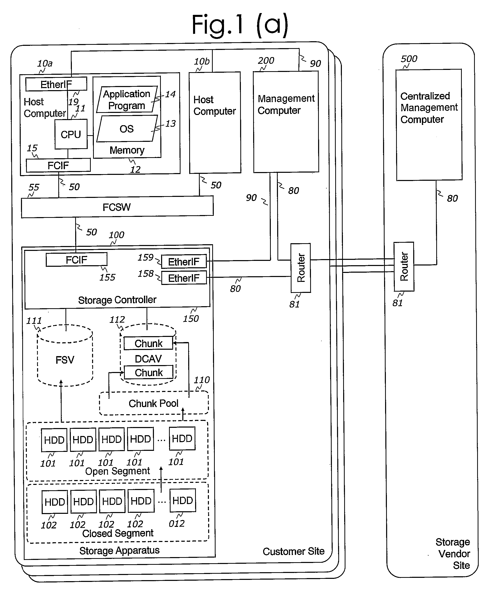
[0044]FIG. 1(a) illustrates an exemplary embodiment of the computerized storage system in which the techniques of this invention are applied. The computerized storage system of the aforesaid first embodiment includes:

Host Computer 10:

[0045]In an embodiment of the inventive technique, at least one host computer 10 is connected to the storage apparatus 100 via data network 50. In the embodiment shown in FIG. 1, two host computers 10a, 10b are so connected. The host computers 10 execute at least one operating system (OS) 13. As it will be appreciated by those of skill in the art, the present invention is not limited to any specific OS 13. Any suitable operating systems, such as Windows, Unix, Linux and the like may be employed as the OS 13. Also, an application 14 may be executed by the host computer 10 under the direction of the OS 13. Files and data for the OS 13 and the application 14 are stored in one or more storage volumes, which are provided by the storage apparatus 100. The...

second embodiment

em Configuration

[0123]FIG. 19 illustrates an exemplary embodiment of the information system in which another method of this invention can be applied. The description below will emphasize the differences between the first embodiment described above and the second embodiment. Specifically, in the second embodiment of the inventive system, two more storage apparatuses 100b and 100c are provided in addition to the storage apparatus 100a of the first embodiment, see FIG. 19. These three storage apparatuses are interconnected by a Fibre Channel switch 56, see FIG. 19. To this end, the storage apparatus 100a is provided with the FCIF 157a for connecting it to the other storage apparatuses. Likewise, the storage apparatus 100b is provide with the FCIF 157b connected to the Fibre Channel switch 56. Thus, the two storage apparatuses 100a and 100b are connected to the storage apparatus 100c via the FCSW 56.

[0124]In the second embodiment, the storage apparatus 100a incorporates multiple volumes...

third embodiment

tion

[0143]FIG. 23 illustrates yet another exemplary embodiment of the information system in which the method of this invention can be applied. The difference between the second embodiment and the third embodiment will now be described in detail. Specifically, in the third embodiment, a storage apparatus 100d is located at the storage vendor site and not at the customer site as in the second embodiment. A remote data network 70 is provided for interconnecting the storage apparatus 100a in the customer site and the storage apparatus 100d in the storage vendor site. The remote data network 70 in the third embodiment is implemented using the Fibre Channel technology. However, the inventive concept is not limited to any specific networking system and other network interfaces, such as Ethernet and the like, can also be utilized.

[0144]To enable the remote data network 70, in the third embodiment, the two routers 71 are used. Also in the third embodiment, the storage apparatus 100a has a re...


PUM


Abstract

The system is composed of the storage apparatuses with dynamic chunk allocation capabilities, the centralized management computer. Some storage apparatuses have the extra HDDs or volumes for providing extra capacity (extra chunks), which are concealed by a secret key. The storage apparatus with the closed segment has the key management program and key management table. The centralized management computer has the storage on demand management program, the pending request table, the priority table and the master key table. The storage apparatus may connect to the other storage apparatuses for sharing the extra capacities in the closed segment. The storage apparatus issues the chunk addition request to the centralized management computer. The centralized management computer provides a key according to the priority table and the master key table. The centralized management computer may provide the key according to the chunk consumption rate reported by the storage apparatus and/or remaining capacity in the other storage apparatuses.

Description

DESCRIPTION OF THE INVENTION [0001]1. Field of the Invention[0002]This invention is related to storage resource management and, more specifically, to techniques for adding new storage capacity to a storage device.[0003]2. Description of the Related Art[0004]Recently, storage systems with dynamic chunk allocation capability have been developed to reduce waste of physical blocks in storage volumes. The aforesaid method for providing dynamic chunk allocation capability for storage devices is disclosed in U.S. published patent application No. 20040162958, titled “Automated on-line expansion method for storage device.” Specifically, the storage system with dynamic chunk allocation capability has volumes, however no physical blocks are allocated to the volumes initially. The storage system allocates a chunk from a chunk pool when a write command is received, which is issued by host computers. If a chunk has already been allocated to area requested by the write command, then no chunk is al...

Claims


Application Information

Patent Timeline
Patent Type & Authority Applications(United States)
IPC IPC(8): G06F12/02G06F12/00G06F12/14G06F21/62G06F21/80
CPCG06F3/0604G06F3/062G06F3/067G06F3/0644G06F3/0665G06F3/0637G06F3/0631
Inventor KANEDA, YASUNORIYAMAMOTO, AKIRA
Owner HITACHI LTD
Why Eureka
Try Eureka