Apparatus for Collecting Smoke and Dust With a Deodorizing Function and a Deodorizing and Filtering Unit

Inactive Publication Date: 2009-02-19
SINTOKOGIO LTD
View PDF24 Cites 9 Cited by
  • Summary
  • Abstract
  • Description
  • Claims
  • Application Information

AI Technical Summary

Benefits of technology

[0043]It is apparent from the explanations of the above paragraphs that this invention can provide an apparatus for collecting smoke and dust with a deodorizing function which can reduce the space for installing such an apparatus, increase the life of such a filter, and improve the efficiency of such a deodorization.
[0044]According to this invention, since the filtering means and the deodori

Problems solved by technology

Thus, since the entire apparatus becomes bigger, it becomes a problem in that a large space for installing it is required.
Further, when the performance of the deodorizer of the deodorizing means is impaired by using the apparatus for a certain time, a large amount of odors accumulate in the filter made of the metal.
Since the filtering means and the deodorizing means are separately disposed in the apparatus, it also becomes a problem in that two par

Method used


Image

  • Apparatus for Collecting Smoke and Dust With a Deodorizing Function and a Deodorizing  and Filtering Unit
  • Apparatus for Collecting Smoke and Dust With a Deodorizing Function and a Deodorizing  and Filtering Unit
  • Apparatus for Collecting Smoke and Dust With a Deodorizing Function and a Deodorizing  and Filtering Unit

Examples


embodiment 1

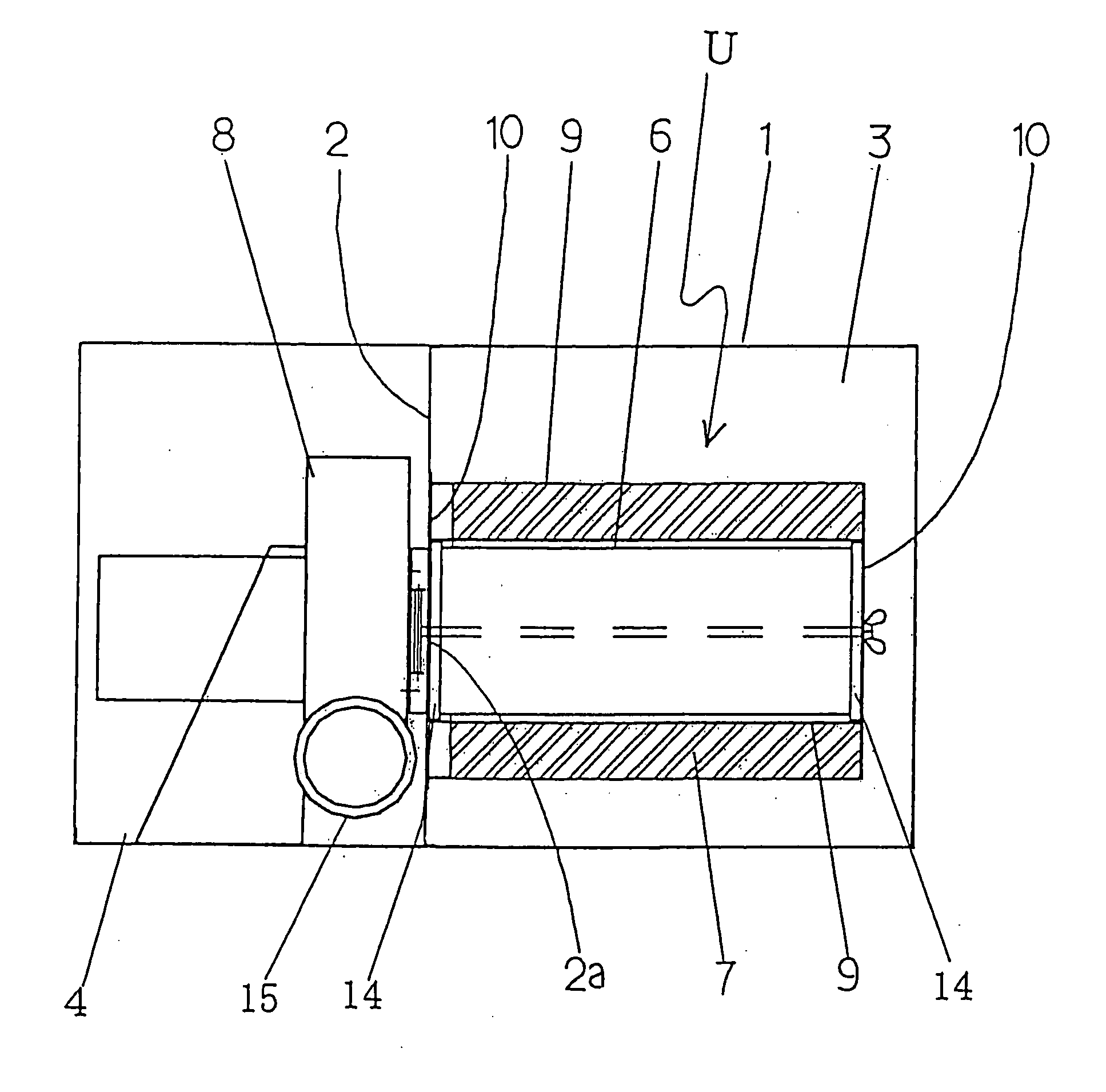
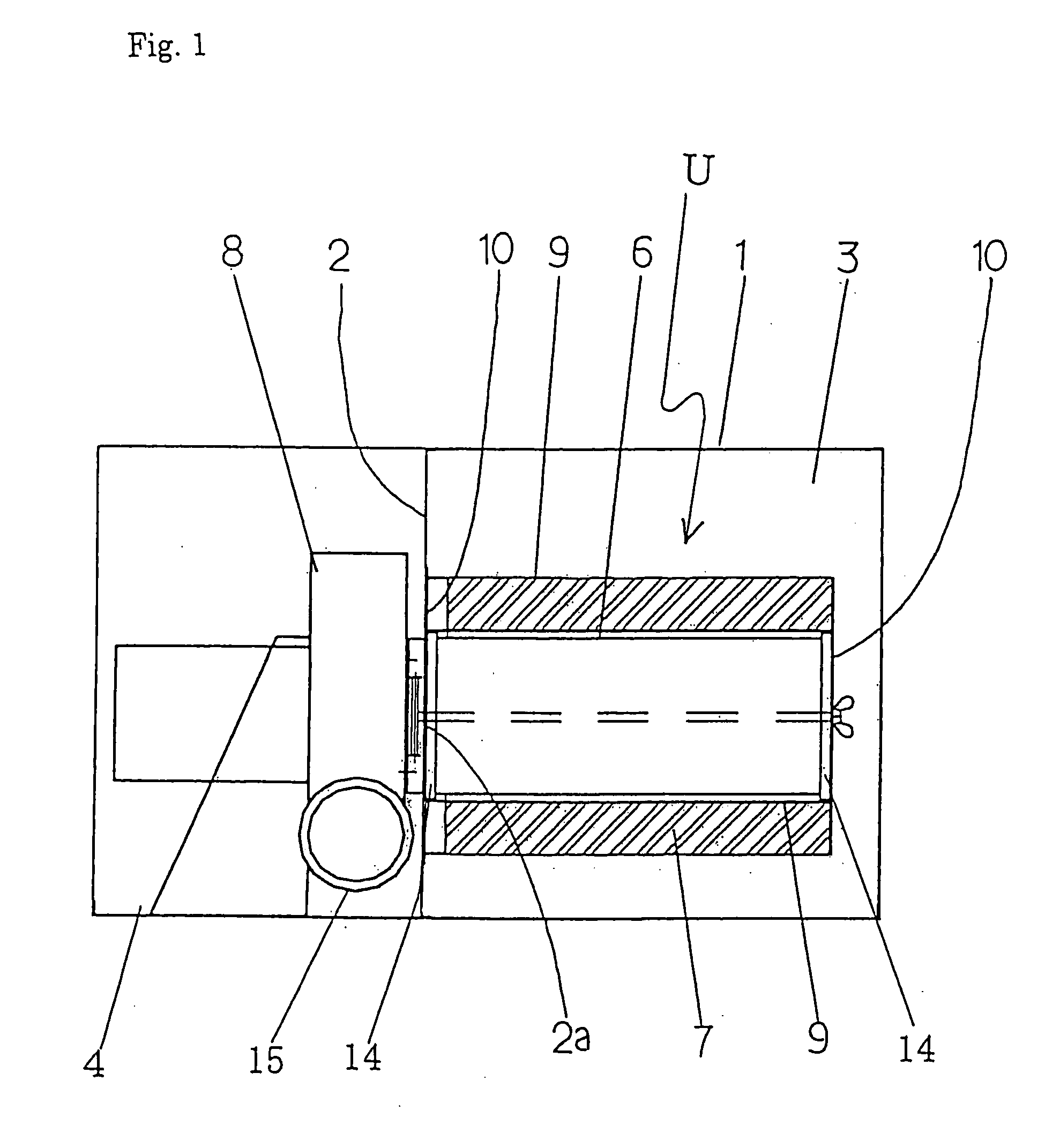
[0058]First, embodiment 1 of this invention is explained based on FIGS. 1-4. In FIGS. 1 and 2, number 1 denotes a housing having a rectangular box structure (the casing of the main body of the apparatus). The internal space of the housing 1 is separated into a space for deodorizing and filtering exhaust gas 3 and a space for discharging exhaust gas 4 by a bulkhead 2. Thus, the exhaust gas sucked into the space for deodorizing and filtering 3 must pass through a deodorizing means and a filtering means, which are explained in detail below, in order to enter the space for discharging.

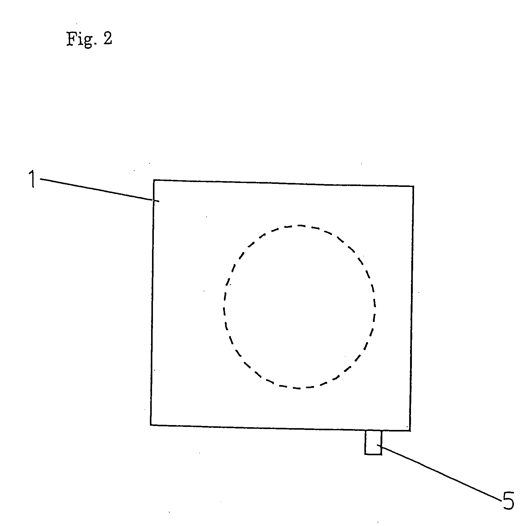
[0059]An intake 5 is disposed at the side wall of the space for deodorizing and filtering 3. The exhaust gas can be sucked into the housing 1 through the intake 5. (See FIG. 2.)

[0060]In the space for deodorizing and filtering 3, a filtering means 6 for filtering the exhaust gas having a cylindrical shape is removably mounted on the bulkhead 2. One side of the filtering means 6, which has openings at both i...

embodiment 2

[0077]FIGS. 5-8 show embodiment 2 of an apparatus with a deodorizing function for collecting smoke and dust. The apparatus is comprised of a housing 1, a deodorizing and filtering unit U, an air blower 8 acting as a vacuuming means, and a control panel E. The apparatus can be freely moved, since casters 1a (not shown in FIG. 7) are mounted on the bottom surface of the housing 1. The housing 1 is constituted of the casing of the main body of the apparatus and has a rectangular box structure. A front panel 1b is fixed to the housing 1 by opening and closing fittings disposed at the four corners of the panel 1b so that the panel 1b can be easily removed from the housing 1. Further, an upper panel 1c is fixed to the housing 1 by magnets and fittings disposed at the upper surface of the housing 1 and the inner surface of the upper panel 1c so that the panel 1c can be easily removed from the housing 1.

[0078]The inner space of the housing 1 is divided, by the bulkhead 2 having the opening ...


PUM

PropertyMeasurementUnit
Lengthaaaaaaaaaa
Sizeaaaaaaaaaa
Specific surface areaaaaaaaaaaa

Abstract

This invention can provide the apparatus for collecting smoke and dust with a deodorizing function which has an excellent capability of maintenance, an improved deodorizing and silencing effect.
The apparatus is comprised of: a bulkhead having an opening and disposed in the housing to separate a space for deodorizing and filtering exhaust gas from a space for discharging exhaust gas,
    • a vacuuming means for vacuuming the exhaust gas disposed in the space for discharging and communicated with the opening of the bulkhead,
    • a filtering means for filtering the exhaust gas disposed in the space for deodorizing and filtering and communicated with the vacuuming means through the opening of the bulkhead, and
    • a deodorizing means for deodorizing the exhaust gas concentrically disposed at the outer side of the filtering means.

Description

TECHNICAL FIELD[0001]This invention relates to an apparatus for collecting smoke and dust with a deodorizing function and a deodorizing and filtering unit. Particularly, this invention relates to an apparatus for collecting smoke and dust with a deodorizing function and a deodorizing and filtering unit which deodorizes and collects evaporable exhaust gas that includes an odoriferous substance in addition to dust, wherein the gas and the dust are generated when products are worked by a laser-tooling machine, for example. Then, the deodorized and filtered exhaust gas is discharged to the outside of the apparatus.BACKGROUND OF THE INVENTION[0002]When products made from resin or rubber are worked by a laser-tooling machine, gas that includes an odoriferous substance and dust, such as fumes, is generated from the working surfaces of the products. For example, there is an apparatus disclosed in Patent Document 1 for treating exhaust gas. It discloses an apparatus comprising a blowing mean...

Claims


Application Information

Patent Timeline
IPC IPC(8): B01D46/52B01D53/81B01D53/38
CPCA61L9/014B01D46/0036B01D2257/90B01D46/2411B01D46/521B01D46/0038
Inventor TAKAYANAGI, KEISUKESUZUKI, TOMOYUKIIKENO, HIDENORI
Owner SINTOKOGIO LTD
Why Eureka
Try Eureka