Systems and Methods for Rotor/Wing Aircraft

a technology of rotor/wing aircraft and system, applied in the direction of aircraft navigation control, transportation and packaging, efficient propulsion technologies, etc., can solve the problem of % of power availabl

Inactive Publication Date: 2009-02-19
THE BOEING CO
View PDF95 Cites 42 Cited by
  • Summary
  • Abstract
  • Description
  • Claims
  • Application Information

AI Technical Summary

Benefits of technology

[0007]In one embodiment, an aircraft includes an airframe, a rotor / wing, a high-lift canard and tail, a propulsion system, and a power-takeoff assembly that enable the aircraft to conduct rotary-wing flight, fixed wing flight and smoothly transition between the two modes. In some implementations, the aircraft may further include a rotatable aft nozzle that is configured to controllably vector engine thrust so as to supplement the lift required from the rotor / wing during rotary-wing flight.
[0008]In another embodiment, a drive assembly is replaced by a radial inflow turbine configured to extract work from the propulsion system for the purpose of rotating the rotor / wing to produce lift during rotary-wing flight. The radial inflow turbine can be selectively by-passed for the purpose of producing thrust during fixed-wing flight. A high-lift canard and tail enable smooth transition between the two modes. In further embodiments, a rotatable aft nozzle is included in the assembly with the radial inflow turbine.

Problems solved by technology

Coriolis losses associated with accelerating the propulsive gases radially as the rotor blade spins consumes up to 40% of power available.

Method used


Image

  • Systems and Methods for Rotor/Wing Aircraft
  • Systems and Methods for Rotor/Wing Aircraft
  • Systems and Methods for Rotor/Wing Aircraft

Examples


Embodiment Construction

[0021]Many specific details of certain embodiments of the disclosure are set forth in the following description and in FIGS. 1-12 to provide a thorough understanding of such embodiments. One skilled in the art, however, will understand that the present disclosure may have additional embodiments, or that the present disclosure may be practiced without several of the details described in the following description.

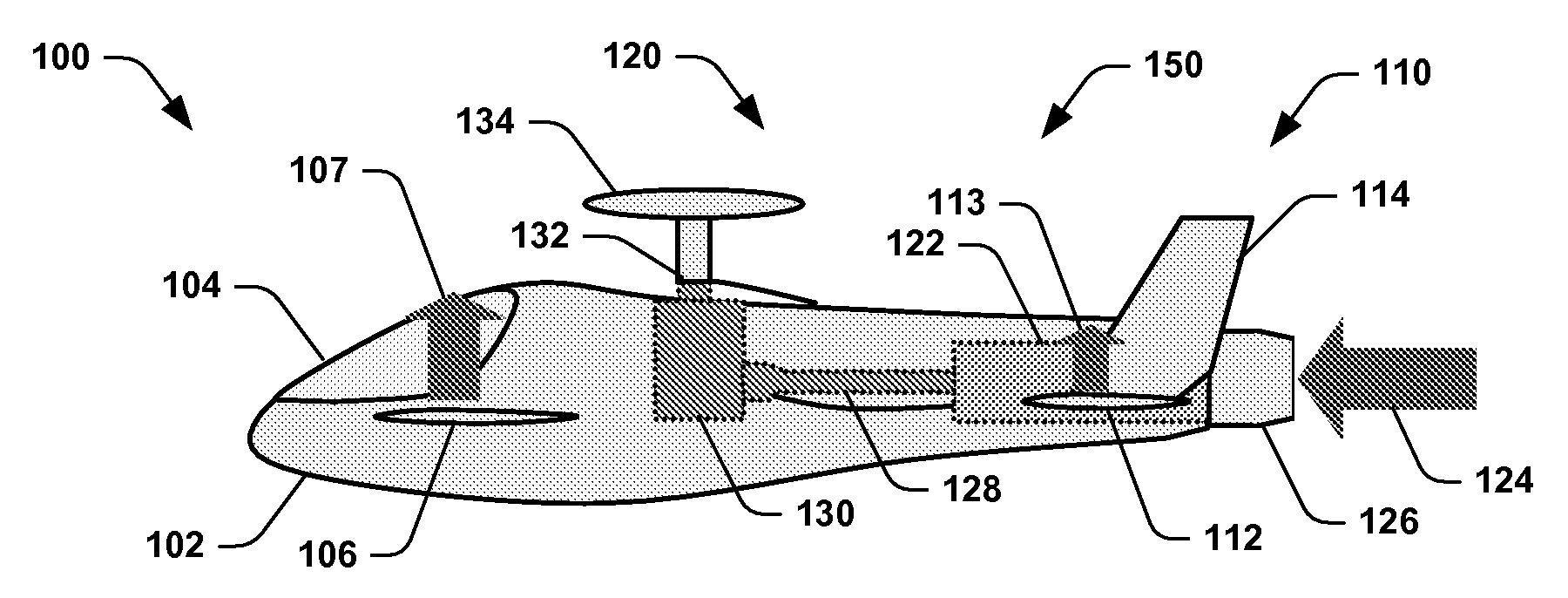
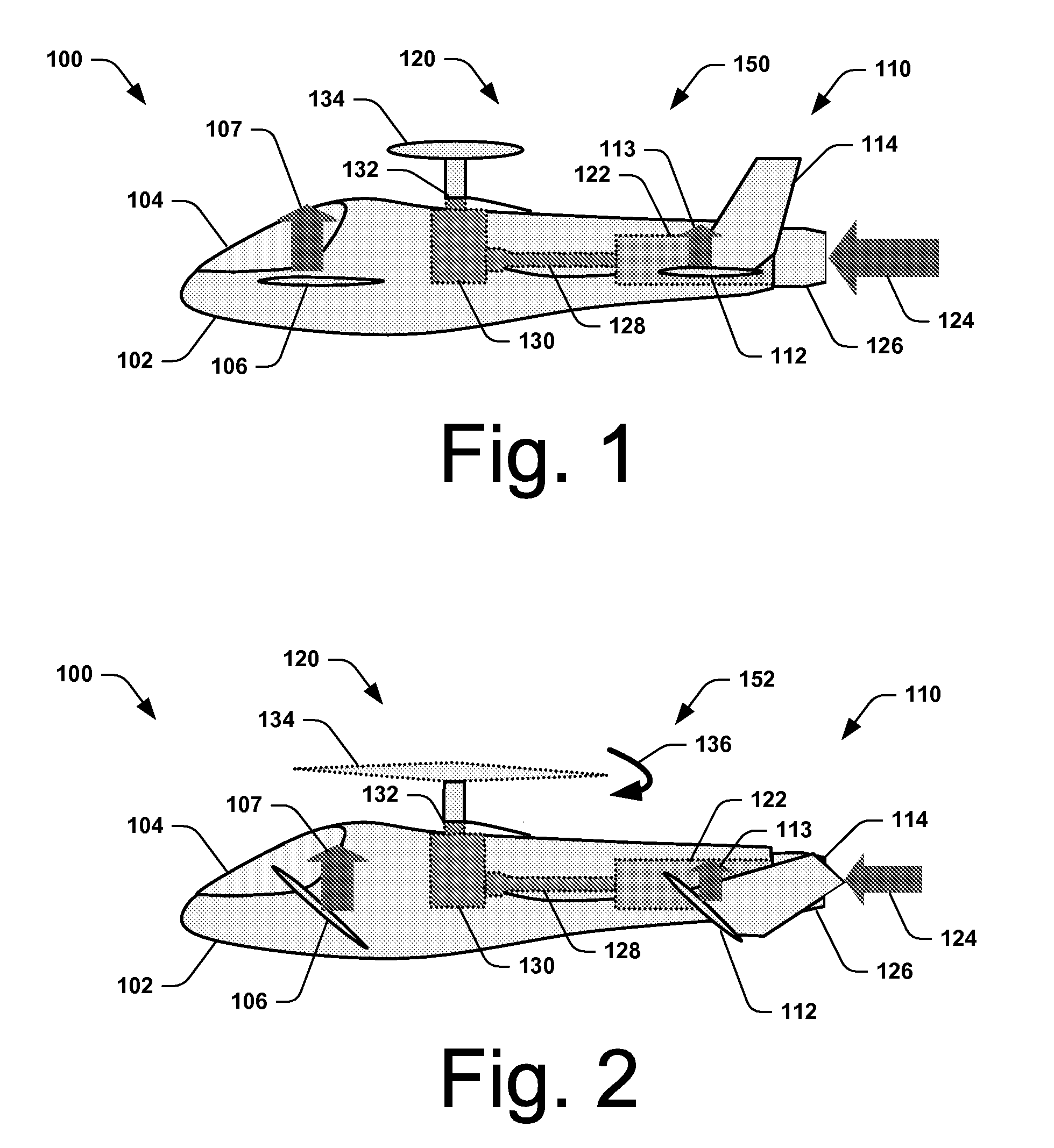
[0022]FIG. 1 is a side view of an aircraft 100 in a fixed-wing mode 150 of operation in accordance with an embodiment of the present disclosure. In this embodiment, the aircraft 100 includes a fuselage 102 of an airframe defining a cockpit portion 104. A canard 106 extends outwardly from each lateral side of the fuselage 102 (one visible). The aircraft 100 further includes a tail assembly 110 having a horizontal tail surface 112 that extends outwardly from each lateral side of the fuselage 102 (one visible), and a vertical tail surface 114 that extends upwardly from each hori...


PUM


Abstract

Systems and methods for rotor/wing aircraft are disclosed. In one embodiment, an aircraft includes an airframe, a high-lift canard and tail, a rotor/wing, a propulsion system, and a drive assembly. The drive assembly, which may include a radial inflow turbine, is configured to extract work from the propulsion system to selectively rotate the rotor/wing assembly thus enabling the aircraft to conduct rotary-wing flight, fixed wing flight as well as smoothly transition between the two modes of flight.

Description

CROSS REFERENCE TO RELATED APPLICATIONS[0001]This patent application is a continuation-in-part application of commonly-owned U.S. patent application Ser. No. 11 / 265,655 entitled “Rotor-Wing Aircraft Having an Adjustable Tail Nozzle” filed on Nov. 2, 2005, now issued as U.S. Pat. No. ______ on ______, which application and issued patent is incorporated herein by reference.FIELD OF THE INVENTION[0002]This disclosure relates to systems and methods for rotor / wing aircraft.BACKGROUND[0003]Higher performance rotary wing aircraft are sought. A stopped-rotor (or rotor / wing) aircraft like that shown in U.S. Pat. No. 3,327,969 offers the ability to hover like a helicopter plus the promise of achieving the high speeds of a fixed-wing aircraft by stopping the rotor's rotation while in flight and allowing it to act as a fixed wing.[0004]Another prior art example of a stopped-rotor aircraft, the Canard Rotor / Wing (CRW) concept (U.S. Pat. No. 5,454,530), combines a reaction-driven, stoppable-rotor...

Claims


Application Information

Patent Timeline
Patent Type & Authority Applications(United States)
IPC IPC(8): B64C27/22
CPCB64C3/385B64C15/02B64C15/14B64C27/82B64C27/24B64C27/26Y02T50/145B64C27/18Y02T50/10
Inventor RICHARDSON, STEVEN D.WALLISER, ERIC W.
Owner THE BOEING CO
Why Eureka
Try Eureka