Bushing and Lantern Ring for Rotary Fluid Pumping Equipment

a technology of rotary fluid pumping equipment and lantern ring, which is applied in the direction of engine seals, liquid fuel engine components, non-positive displacement fluid engines, etc., can solve the problems of contaminated flush water supply, need treatment, and large flushing requirements, so as to reduce the amount of flushing, reduce the amount of particulate matter, and facilitate fluid transfer. efficient

Inactive Publication Date: 2009-02-19
PATTON CHRISTOPHER S +2
View PDF14 Cites 15 Cited by
  • Summary
  • Abstract
  • Description
  • Claims
  • Application Information

AI Technical Summary

Benefits of technology

[0009]It is therefore an object of the present invention to provide a device that reduces the amount of flush required in pumping applications involving fluid-dispersed particulates, or slurries. It is also an object to provide an effective means of reducing the amount of particulate matter and air that becomes tr...

Problems solved by technology

However, in applications where the fluid being pumped contains abrasives or particulate matter, the requirement for flush supply is much greater.
This presents several problems during pump operation.
For instance, the flush water supply may become contaminated and require treatment.
The machining of these spiral grooves is difficult, and since centrifugal pumps may rotate in either clockwise or counter-clockwise direction, the hand of the spiral groove must suit the rotation of the equipment to ensure that the fluid and contaminants carried thereby spiral inwardly toward the shaft.
In addition, the spiral design of this device only allows for one exit groove which, when blocked, reduces or eliminates the effectiveness of the device.
Such devices, however, are not useful for clearing fibrous material from pump seal chambers, and cannot be used at all in packing applications.
In addition, the device can only be manufactured from a li...

Method used


Image

  • Bushing and Lantern Ring for Rotary Fluid Pumping Equipment
  • Bushing and Lantern Ring for Rotary Fluid Pumping Equipment
  • Bushing and Lantern Ring for Rotary Fluid Pumping Equipment

Examples


Embodiment Construction

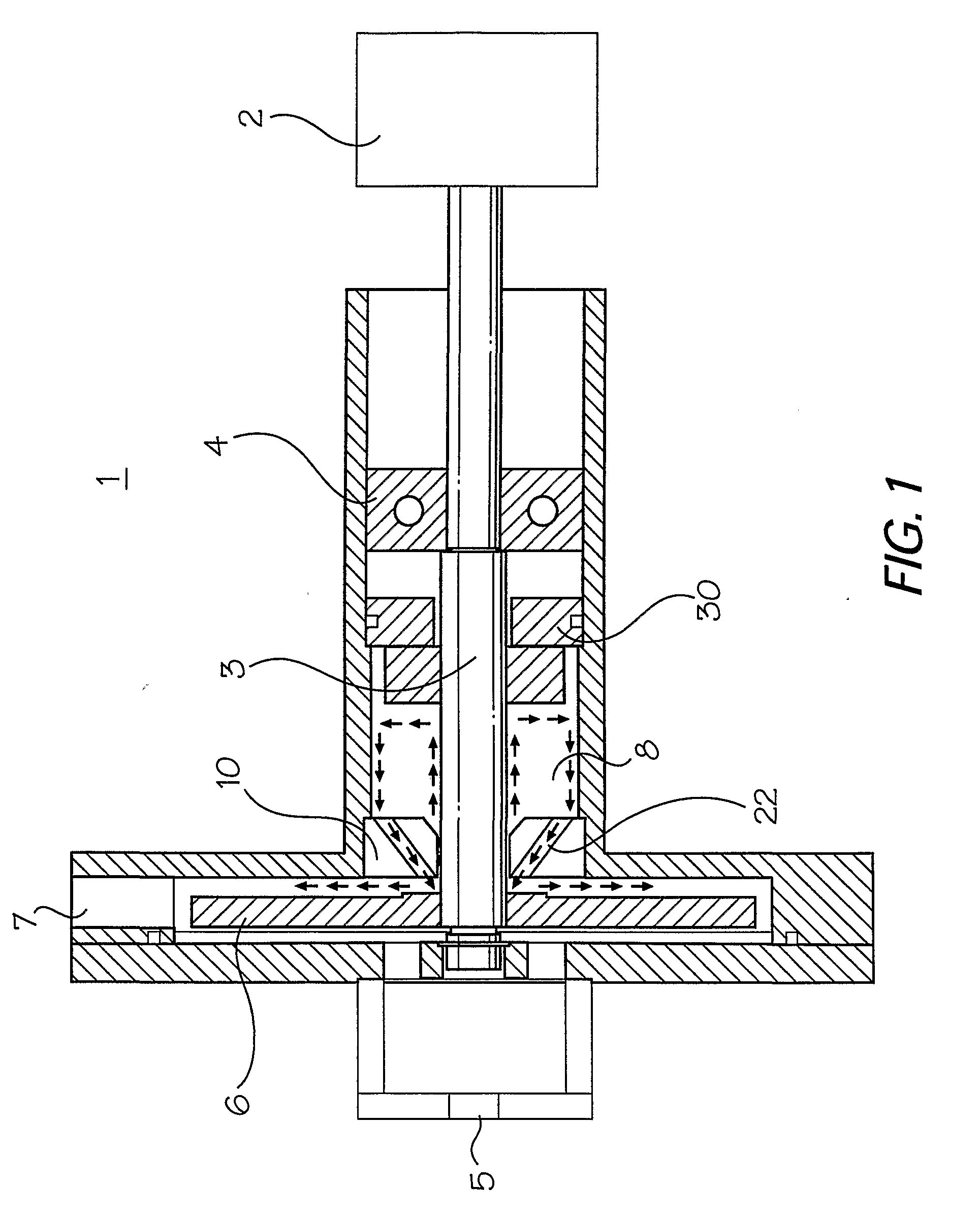
[0024]FIG. 1 illustrates one possible operating environment for the throat bushing of the present invention, involving a standard centrifugal pump (1) with a mechanical seal arrangement. As shown, the pump (1) is driven by an electric motor (2), which in turn drives a rotary shaft (3) supported by bearings within a bearing housing (4). The shaft (3) is connected to an impeller (6) at its terminal end. As the impeller (6) is rotated by the shaft, water or other fluid is drawn into the pump housing through an inlet (5), and pumped out to the environment through pump outlet (7).

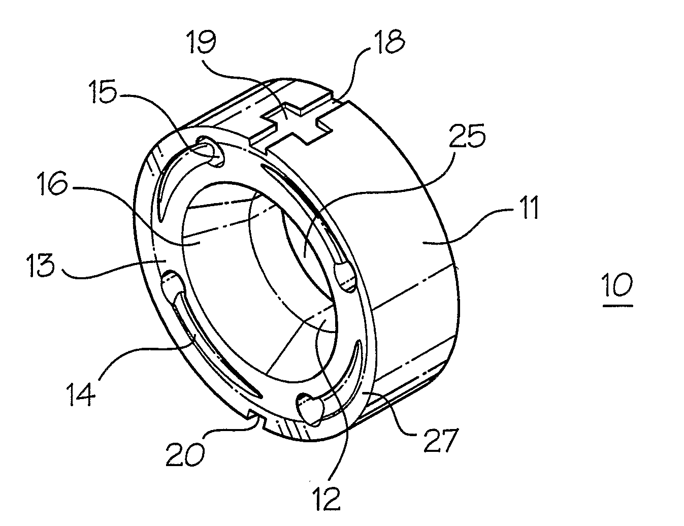
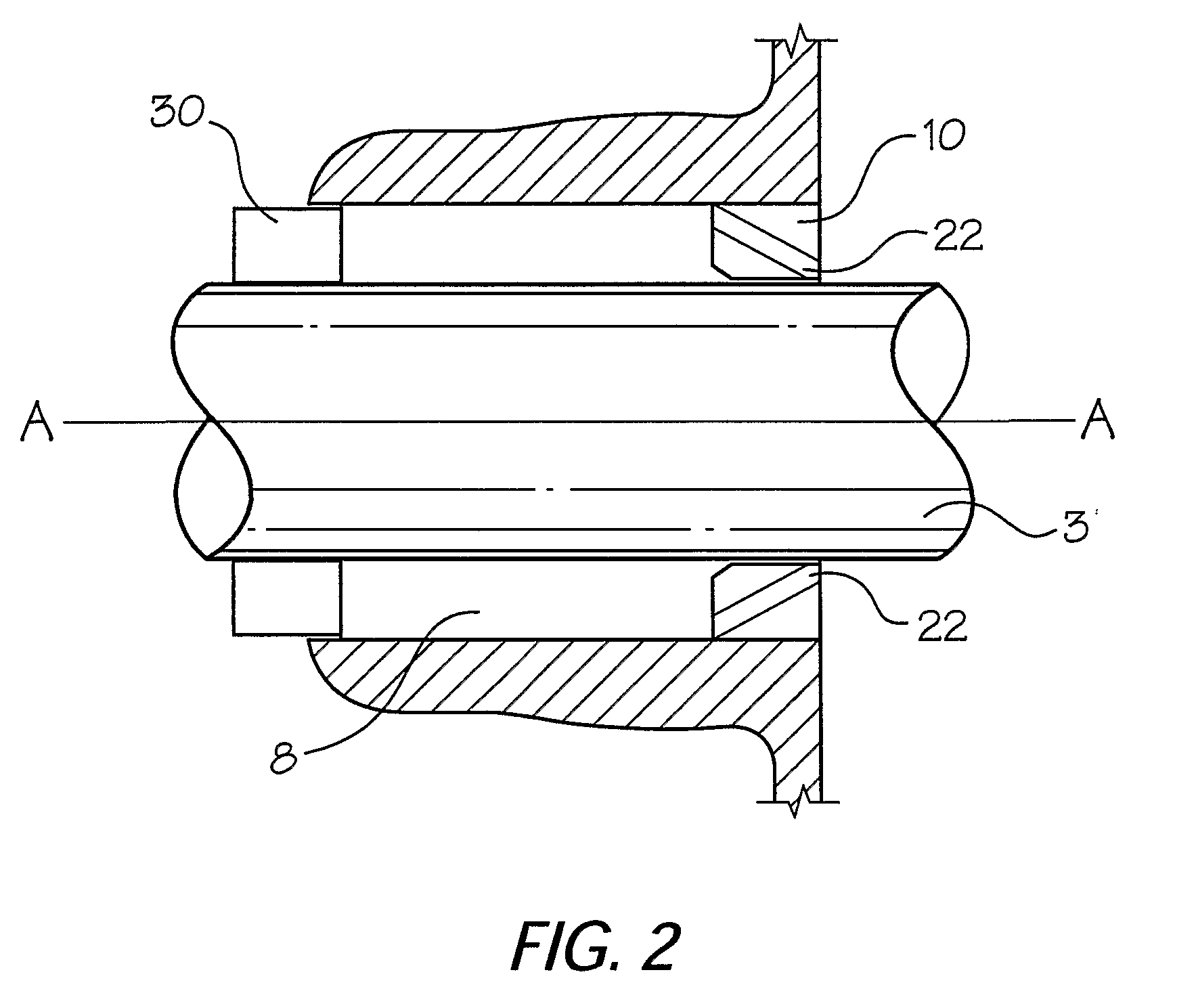
[0025]As illustrated in FIG. 1, and in expanded view in FIG. 2, the throat bushing (10) of the present invention is placed in the throat of a seal chamber (8), with the pump shaft (3) running through its bore. The axis of rotation of pump shaft (3) is represented by line A-A shown in FIG. 2. A mechanical seal (30) is positioned at the rear end of the seal chamber (8). Tangential channels (22) bored through the t...


PUM


Abstract

A throat bushing (10, 54) for use in a seal chamber (8) or stuffing box (56) of rotary fluid equipment. The throat bushing defines a first face (13, 60) and a second face (21, 62), an outer surface (11) dimensioned to be received with a tight fit within a throat or bore of the seal chamber (8) or stuffing box (56), and a bore (25) therethrough dimensioned to receive a rotary shaft (3) with clearance to permit free rotation of the rotary shaft (3) therein. The throat bushing comprises at least one tangential channel (22) therethrough leading tangentially from the first face (13, 60) proximal to the outer surface (11), through to the second face (21, 62), proximal to an inner annular surface (12) of the throat bushing bore (25).

Description

FIELD OF THE INVENTION[0001]This invention relates to improvements in throat bushings commonly employed in the pump housing of centrifugal pumps and other such rotary fluid equipment. The invention further relates to devices which reduce pump flush requirements or extend the amount of time between repairs. More particularly, the invention relates to a throat bushing having at least one channel therethrough to facilitate the evacuation of air and particulate matter trapped in the pump seal chamber or stuffing box, back out towards the volute of the pump housing.BACKGROUND OF INVENTION[0002]Throat bushings are well known and commonly employed within the pump housings of centrifugal pumps and other such rotary fluid equipment. They are typically provided to form a restrictive close clearance around the motor shaft or shaft sleeve, in order to separate the impeller in the pump chamber, or volute, from the seal chamber or stuffing / packing box. The throat bushing will be located between t...

Claims


Application Information

Patent Timeline
IPC IPC(8): F16J15/18
CPCF16J15/183F04D29/106
Inventor PATTON, CHRISTOPHER S.VALLEY, DAVID W.LLOYD, ARNOLD T.
Owner PATTON CHRISTOPHER S
Why Eureka
Try Eureka