
Piezoelectric transformer type high-voltage power apparatus and image forming apparatus

Active Publication Date: 2009-02-19
HEWLETT PACKARD DEV CO LP
View PDF7 Cites 16 Cited by
  • Summary
  • Abstract
  • Description
  • Claims
  • Application Information

AI Technical Summary

Benefits of technology

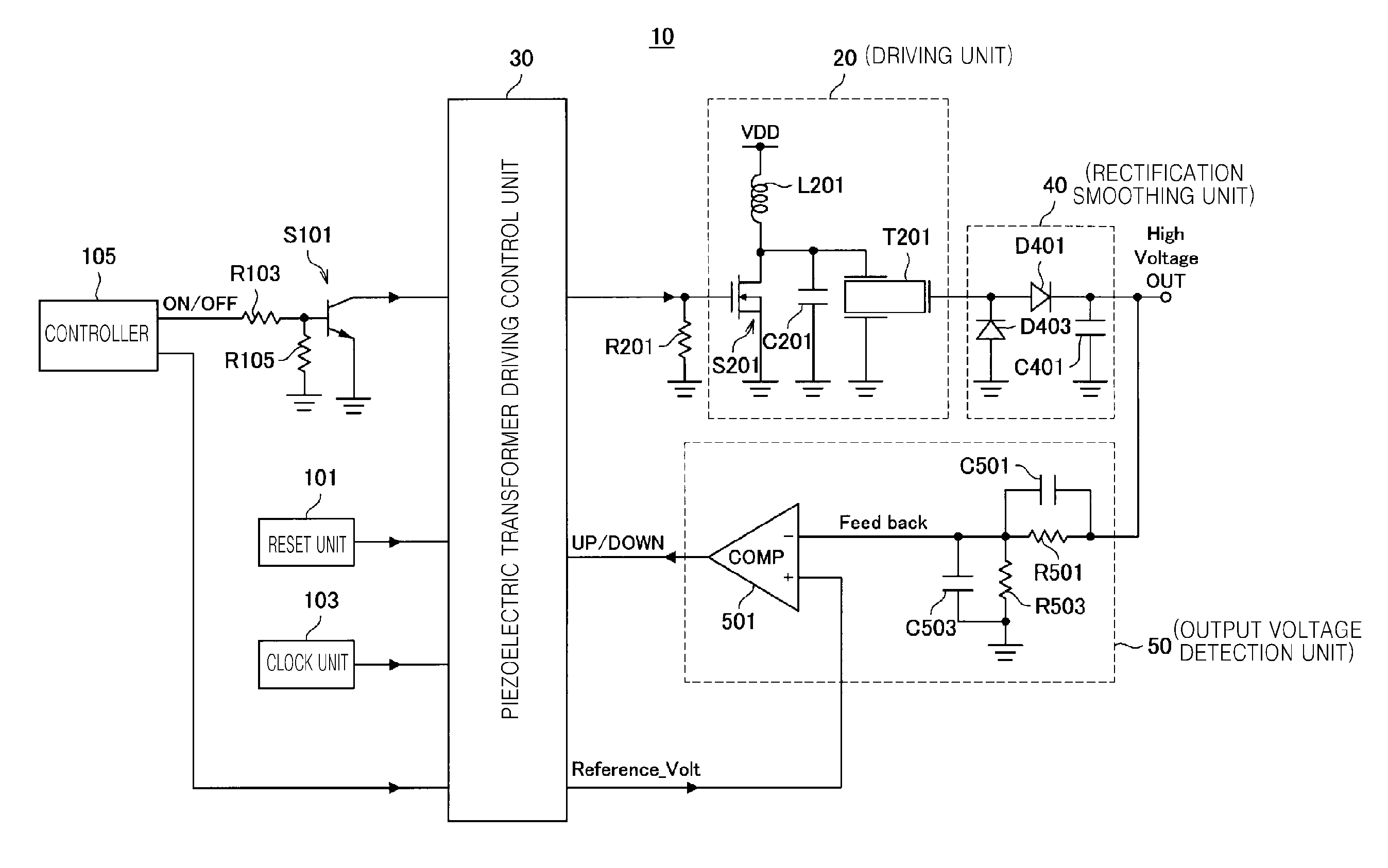
[0012]Several aspects and example embodiments of the present invention provide a high-voltage power source apparatus provided with a piezoelectric transformer and an image forming apparatus in which a stable driving frequency control can be realized without falling into an abnormal oscillation or uncontrollable state, and a stable high-voltage can be output within a short rise time.
[0018]The power source apparatus according to the present invention includes: an output voltage detection unit to compare an output voltage with a reference voltage for controlling the output voltage with a predetermined value, and based on the comparison result, detecting a change of the output voltage representing the change with a digital value; and a driving control unit to perform driving control of the piezoelectric transformer according to the detected digital value. Accordingly, stable frequency control can be performed without falling into an abnormal oscillation or uncontrollable state, and a high-voltage can be output within a short rise time.

Problems solved by technology

However, when this method is used, there are risks of overheating to produce smoke and fire, and a relatively larger electronic transformer compared to a supplied power is required.
Accordingly, it is difficult to reduce the size and weight of the coil-type electronic transformer.
Furthermore, since the piezoelectric transformer is irrespective of combining of a primary side thereof and a secondary side, putting a distance between electrodes of the primary side and the secondary side is possible, mould processing is not necessary, and risks of producing smoke and fire disappear.
However, in the high-voltage power source apparatus using a piezoelectric transformer, frequency control is performed by an analogue signal processing circuit, and therefore, a frequency control operation is unstable.
That is, if a control voltage is rapidly changed in order to quickly raise (or drop) an output voltage of the high-voltage power source apparatus, a resonant frequency of the piezoelectric transformer is exceeded and it is impossible to control the output voltage.
Also, when power equal to or greater than a capacity of a piezoelectric transformer is required due to an unpredicted situation, a driving frequency of the piezoelectric transformer exceeds the resonant frequency, and it is impossible to control the output voltage of the piezoelectric transformer, to thereby cause bad image signals to be generated.
Also, even as the output voltage from the piezoelectric transformer cannot be controlled, oscillation of a circuit operation in the high-voltage power source apparatus occurs.
In addition, a delay of a rise time occurs due to a spurious driving frequency from a time when a control signal to turn on the high-voltage power source apparatus is input to an operational amplifier to a time when a desired set output voltage value is reached.
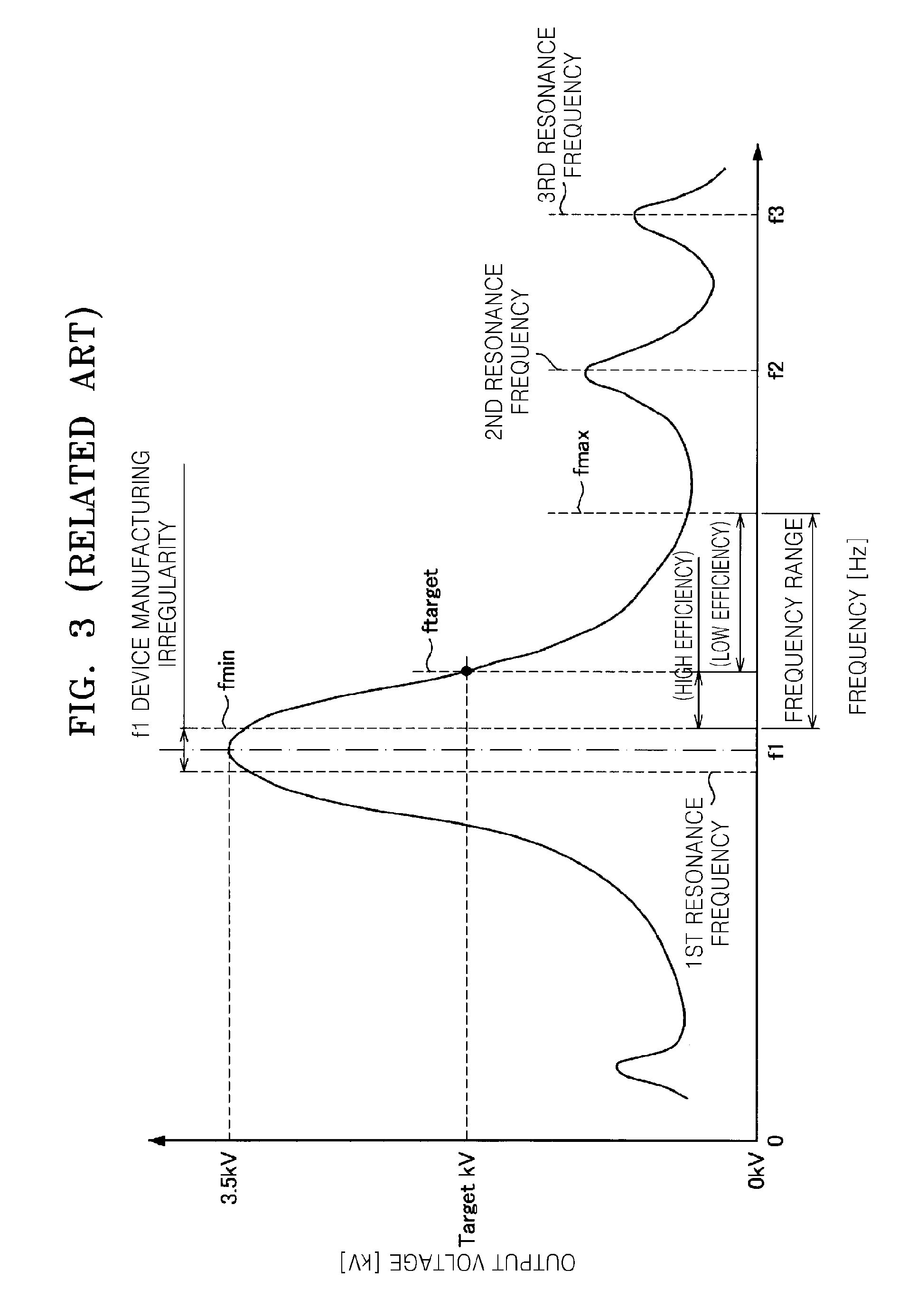
Furthermore, as a plurality of resonant frequency points relative to the output voltages exists for a piezoelectric transformer, in order to increase a range of the output voltages that may be output by the piezoelectric transformer, frequencies in a range that result in low efficiency voltage output would be used, which decreases the overall efficiency of the high-voltage power source apparatus as a whole.
For this reason, it is difficult to achieve a low voltage output of the high-voltage power source apparatus using the piezoelectric transformer.

Method used


Image

  • Piezoelectric transformer type high-voltage power apparatus and image forming apparatus
  • Piezoelectric transformer type high-voltage power apparatus and image forming apparatus
  • Piezoelectric transformer type high-voltage power apparatus and image forming apparatus

Examples


Embodiment Construction

[0040]Reference will now be made in detail example embodiments of the present invention, examples of which are illustrated in the accompanying drawings, wherein like reference numerals refer to the like elements throughout. The example embodiments are described below in order to explain the present invention by referring to the figures.

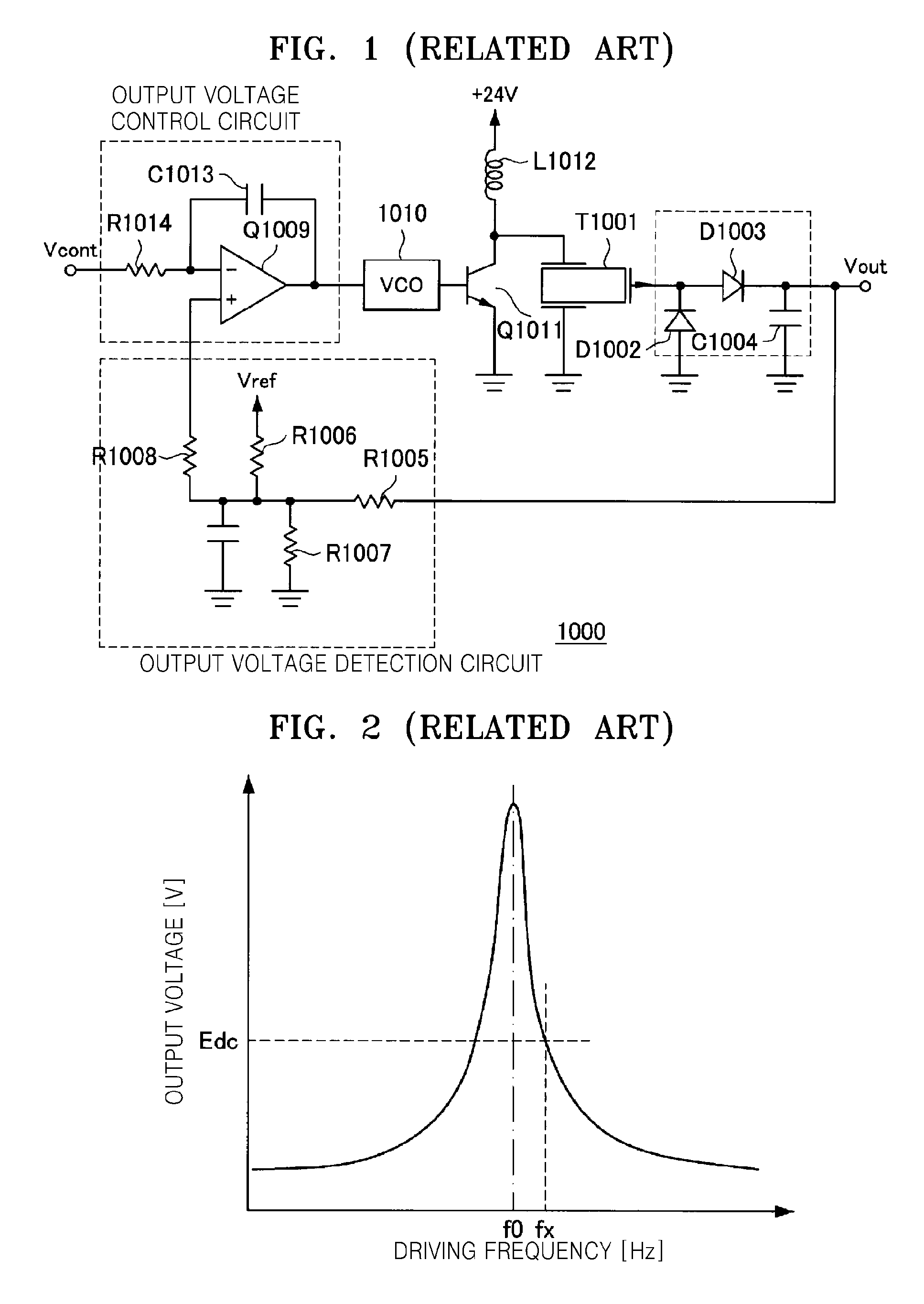
[0041]Before explaining a piezoelectric transformer type high-voltage power source apparatus according to example embodiments of the present invention, a typical high-voltage power source apparatus will be explained with reference to FIGS. 1 through 3 in order to clarify differences in the structures between the piezoelectric transformer type high-voltage power source apparatus according to example embodiments of the present invention and the typical piezoelectric transformer type high-voltage power source apparatus.

[0042]FIG. 1 is a block diagram of a typical high-voltage power source apparatus. In the typical high-voltage power source apparatus, a p...


PUM


Abstract

A piezoelectric transformer high-voltage power source apparatus, in which a driving voltage determined by a value of a driving frequency is applied to a piezoelectric transformer, and thereby an output voltage output by the piezoelectric transformer is provided to a load, includes: an output voltage detection unit to compare an output voltage with a reference voltage for controlling the output voltage, in order to maintain the output voltage at a predetermined value, and based on the comparison result, detecting the change of the output voltage as a digital value; and a driving control unit to perform driving control of the piezoelectric transformer according to the detected digital value. The high-voltage power source apparatus performs stable frequency control without falling into an abnormal oscillation or uncontrollable state, and a high-voltage can be output within a short rise time.

Description

CROSS-REFERENCE TO RELATED APPLICATION[0001]This application claims all benefits accruing under 35 U.S.C. §119 from Japanese Patent Application No. 2007-200793, filed on Aug. 1, 2007, in the Japanese Intellectual Property Office, and Korean Patent Application No. 2007-118097, filed on Nov. 19, 2007, in the Korean Intellectual Property Office, the disclosures of which are incorporated herein by reference.BACKGROUND OF THE INVENTION[0002]1. Field of the Invention[0003]The present invention relates to a power source apparatus using a piezoelectric transformer, and an image forming apparatus thereof.[0004]2. Description of the Related Art[0005]In an image forming apparatus which forms an image in an electronic photographing process, if a direct transfer method is employed to enable a transfer unit to be in contact with a photoreceptor to transfer an image, the transfer unit uses a conductive rubber in the form of a roller having a rotation axis as a conductive body. In this case, drivin...

Claims


Application Information

Patent Timeline
IPC IPC(8): H02M3/335
CPCG03G15/80G03G15/1675H10N30/804
Inventor KONDO, TAKASHI
Owner HEWLETT PACKARD DEV CO LP
Learn More