
Real Time Telecentricity Measurement

a technology of telecentricity and measurement method, applied in the direction of instruments, measurement devices, optics, etc., can solve the problems of insufficient existing calibration techniques, difficult to completely eliminate the relative movement between the optical components of the lithographic apparatus, and degrade the accuracy of the projected pattern

Inactive Publication Date: 2009-02-19
ASML HLDG NV
View PDF5 Cites 6 Cited by
  • Summary
  • Abstract
  • Description
  • Claims
  • Application Information

AI Technical Summary

Benefits of technology

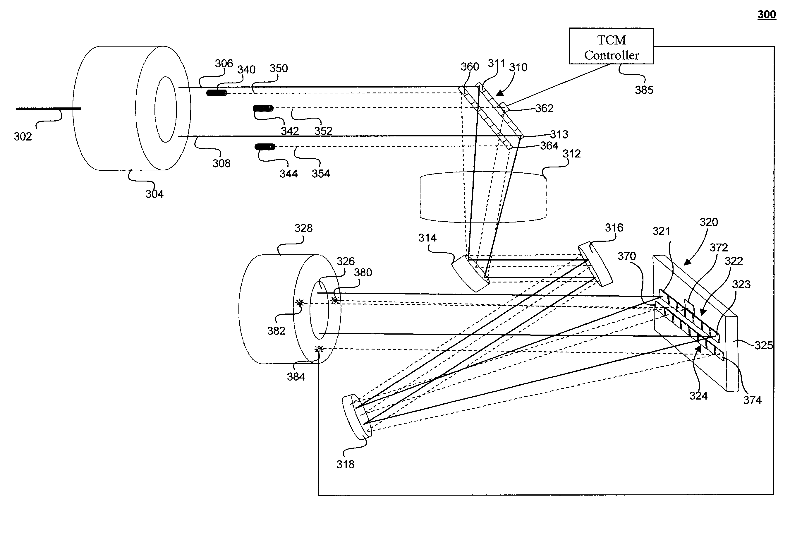
[0009]Systems and methods for measuring and correcting for telecentricity effects a lithographic apparatus without impacting wafer throughput or wasting actinic light are provided.

Problems solved by technology

However, relative movement between the optical components of the lithographic apparatus may affect the alignment of the apparatus and induce telecentricity effects that degrade the accuracy of the projected pattern.
Unfortunately, it is difficult to completely eliminate relative movement between the optical components in lithographic apparatus.
Further, existing calibration techniques are generally insufficient to perform real-time measurement and correction of telecentricity.
As such, existing techniques to measure induced telecentricity in lithographic apparatus make inefficient use of actinic light and reduce the throughput of the lithographic apparatus.

Method used


Image

  • Real Time Telecentricity Measurement
  • Real Time Telecentricity Measurement
  • Real Time Telecentricity Measurement

Examples


Embodiment Construction

[0026]This specification discloses one or more embodiments that incorporate the features of this invention. The disclosed embodiment(s) merely exemplify the invention. The scope of the invention is not limited to the disclosed embodiment(s). The invention is defined by the claims appended hereto.

[0027]The embodiment(s) described, and references in the specification to “one embodiment”, “an embodiment”, “an example embodiment”, etc., indicate that the embodiment(s) described can include a particular feature, structure, or characteristic, but every embodiment cannot necessarily include the particular feature, structure, or characteristic. Moreover, such phrases are not necessarily referring to the same embodiment. Further, when a particular feature, structure, or characteristic is described in connection with an embodiment, it is understood that it is within the knowledge of one skilled in the art to effect such feature, structure, or characteristic in connection with other embodiment...


PUM


Abstract

Systems and methods are provided for measuring and correcting for a given telecentricity in lithographic apparatus. A radiation beam is partitioned into a plurality of beams, each of which is modulated using an array of individually controllable elements and projected onto a portion of a substrate through a projection system. A set of alignment beams are transmitted simultaneously on paths similar to those traversed by the plurality of radiation beams, and a corresponding set of sensors respectively measures an angle and a position of the set of alignment beams proximate an entrance of the projection system. An assembly of telecentricity control mirrors (TCMs) adjusts appropriate ones of the plurality of radiations beams in response to the measurement to correct for induced any detected telecentricity.

Description

BACKGROUND[0001]1. Field of the Invention[0002]The present invention relates to the measurement and correction of telecentricity in a lithographic apparatus.[0003]2. Related Art[0004]A lithographic apparatus is a machine that applies a desired pattern onto a substrate or part of a substrate. A lithographic apparatus can be used, for example, in the manufacture of flat panel displays, integrated circuits (ICs) and other devices involving fine structures. In a conventional apparatus, light is directed to a patterning device, which can be referred to as a mask, a reticle, an array of individually programmable or controllable elements (maskless), or the like. The patterning device can be used to generate a circuit pattern corresponding to an individual layer of an IC, flat panel display, or other device. This pattern can be transferred onto all or part of the substrate (e.g., a glass plate, a wafer, etc.), by imaging onto a layer of radiation-sensitive material (e.g., resist) provided o...

Claims


Application Information

Patent Timeline
Patent Type & Authority Applications(United States)
IPC IPC(8): G01B11/26
CPCG03F7/70191G01B11/26
Inventor KOCHERSPERGER, PETER C.WIENER, ROBERTO B.
Owner ASML HLDG NV
Learn More