Opening mechanism for a flexible container

a flexible container and opening mechanism technology, applied in the direction of containers, flexible covers, liquid dispensing, etc., can solve the problem that fluid cannot be dispensed, and achieve the effect of reducing leakage and being simple to us

Inactive Publication Date: 2009-02-19
ENTAPACK
View PDF19 Cites 13 Cited by
  • Summary
  • Abstract
  • Description
  • Claims
  • Application Information

AI Technical Summary

Benefits of technology

[0012]wherein a circumferential flexible seal is provided within the outlet spout on one of the driver and the outlet spout to engage with the other of the driver and the outlet spout to reduce leakage of fluid between the outlet spout and the driver as the collapsible container is opened.
[0018]wherein a circumferential flexible seal is provided within the outlet spout on one of the driver and the outlet spout to engage with the other of the driver and the outlet spout to reduce leakage of fluid between the outlet spout and the driver as the collapsible container is opened.
[0020]During opening of the collapsible container the pressure of the fluid under gravity tends to force it through any openings to which it has access between the outlet spout and the driver, for example, between the opposed threads thereof. The circumferential flexible seal acts as a barrier, physically reducing the possibility that fluid can leak from the collapsible container through any flow paths formed between the outlet spout and the driver.
[0021]The opening mechanism of the present invention allows the collapsible container to be opened with reduced leakage without the need for a complex valving arrangement and is therefore relatively simple to use. Hitherto, leakage during opening was a particular problem when using drivers having at least 5 threads per inch (2 threads per centimetre (cm)). While these drivers allow for relatively quick advancement of the driver into the outlet spout, they have not been used previously without the valving system described above, because of the leakage problem during opening.

Problems solved by technology

The membrane sealing the outlet spout is punctured by the cutting tool, but fluid cannot yet be dispensed because the cutting tool forms a seal in the cutting assembly.

Method used


Image

  • Opening mechanism for a flexible container
  • Opening mechanism for a flexible container
  • Opening mechanism for a flexible container

Examples


Embodiment Construction

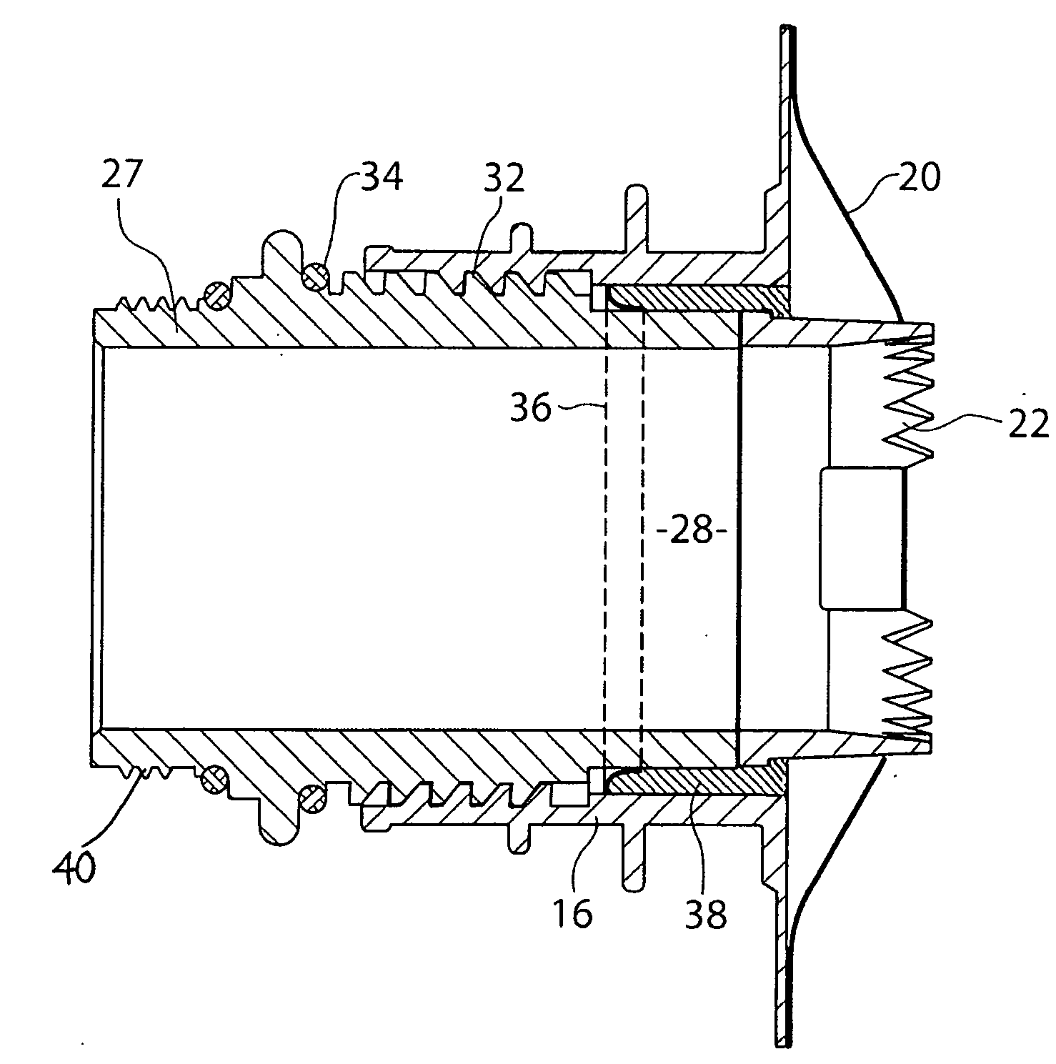
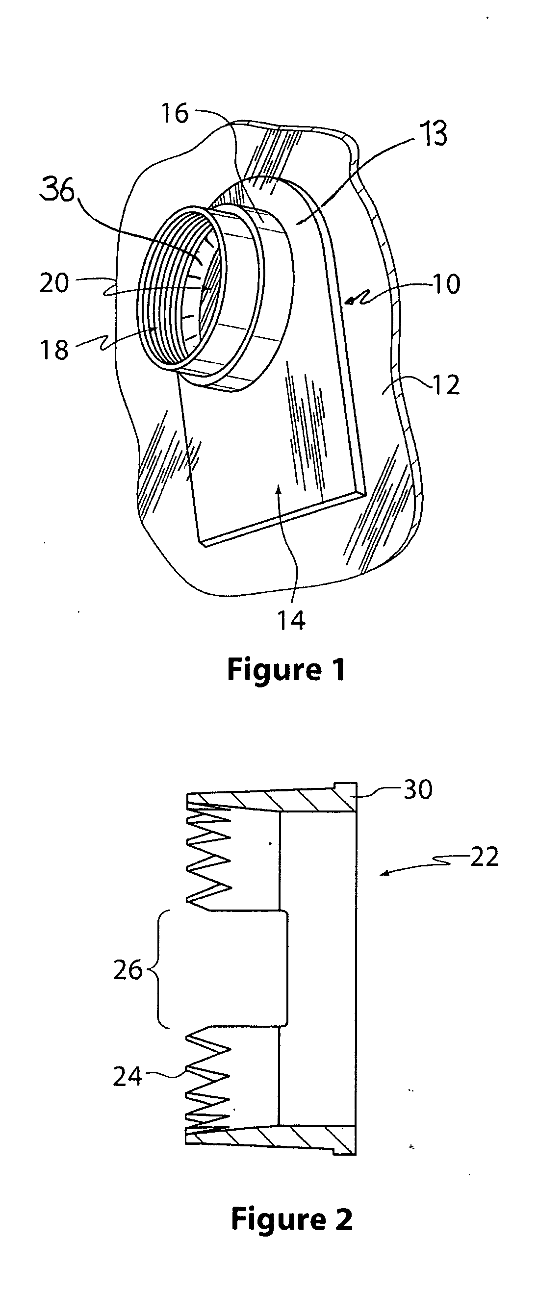
[0030]The collapsible container of the present invention may be made of any suitable film material or laminated films of material as is known in the art. A multilayered film comprising polypropylene or polyethylene film is particularly suitable for this purpose. The collapsible container is preferably shaped generally to correspond with the shape of the rigid container (not shown) in which it is to be housed so that, when full, it will extend to and press against the walls of the rigid container to be supported thereby. Preferably the collapsible container is marginally greater in size than the rigid container to ensure that the collapsible container does not need to support the weight of the contents itself. Neither the rigid container nor the collapsible container form part of the present invention and they will therefore not be described further.

[0031]The collapsible container may include a fluid inlet preferably on its upper wall and through which fluid may be introduced into th...


PUM


Abstract

An opening mechanism for use with a fluid filled collapsible container is disclosed. The mechanism comprises an outlet spout adapted to be joined to a wall of the collapsible container, a perforator for opening the collapsible container through the outlet spout and a driver having a passage therethrough. The driver is received within the outlet spout and screw threadedly engaged therewith for advancement by relative rotation thereof to drive the perforator though the outlet spout to thereby open the collapsible container and permit fluid to be dispensed through the passage. A circumferential flexible seal is provided within the outlet spout on one of the driver and the outlet spout to engage with the other of the driver and the outlet spout to reduce leakage of fluid between the outlet spout and the driver as the collapsible container is opened.

Description

FIELD OF THE INVENTION[0001]The present invention relates to mechanisms used to open flexible containers containing fluids in order that the contents can be dispensed.BACKGROUND[0002]Flexible containers for fluids are known in which there is an outer substantially rigid container and an inner collapsible container for the fluid. The inner collapsible container can be filled with a fluid and the contents can be dispensed without the need for air to enter the inner container thereby to avoid oxidation and deterioration of the contents. For example, wine and other liquids are dispensed from what have become known as bag-in-box containers.[0003]Containers of this type are also known for industrial type applications to package larger quantities of fluids. For example, bulk containers are used to hold in the order of 1,000 litres of liquid or paste. In these containers there is often a pallet such as a wooden pallet or the like supporting an outer substantially rigid container which may b...

Claims


Application Information

Patent Timeline
Patent Type & Authority Applications(United States)
IPC IPC(8): B65D33/38
CPCB65D51/226
Inventor KEEN, STEPHEN ASHTONPAPALUCA, VINCENT
Owner ENTAPACK
Why Eureka
Try Eureka