Formation of shallow junctions by diffusion from a dielectric doped by cluster or molecular ion beams

Active Publication Date: 2009-02-19
TEXAS INSTR INC
View PDF6 Cites 64 Cited by
  • Summary
  • Abstract
  • Description
  • Claims
  • Application Information

AI Technical Summary

Problems solved by technology

Formation of heavily doped shallow regions is problematic because anneals sufficien

Method used


Image

  • Formation of shallow junctions by diffusion from a dielectric doped by cluster or molecular ion beams
  • Formation of shallow junctions by diffusion from a dielectric doped by cluster or molecular ion beams
  • Formation of shallow junctions by diffusion from a dielectric doped by cluster or molecular ion beams

Examples


Embodiment Construction

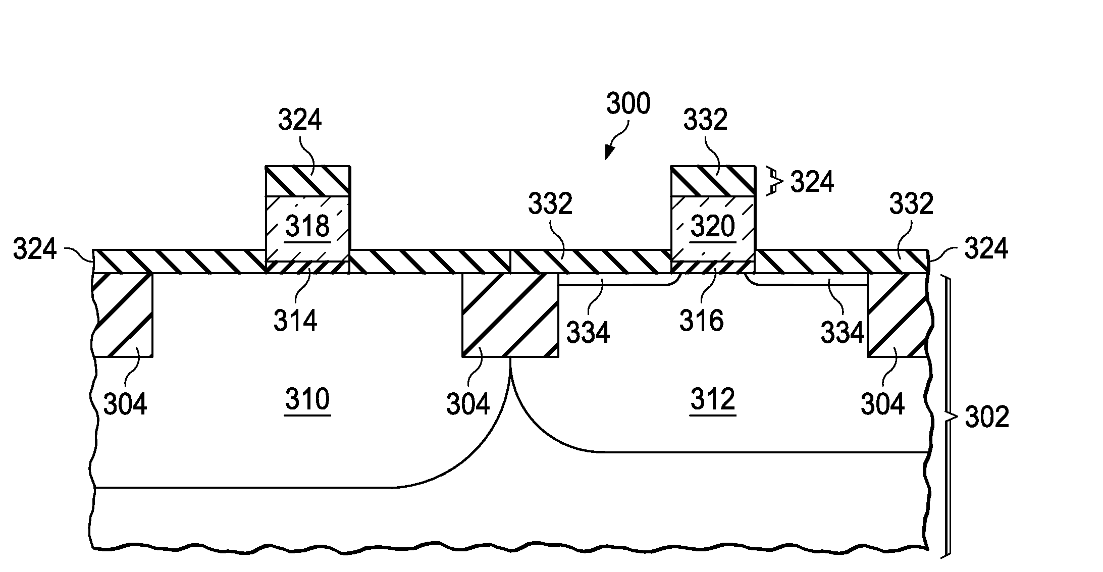
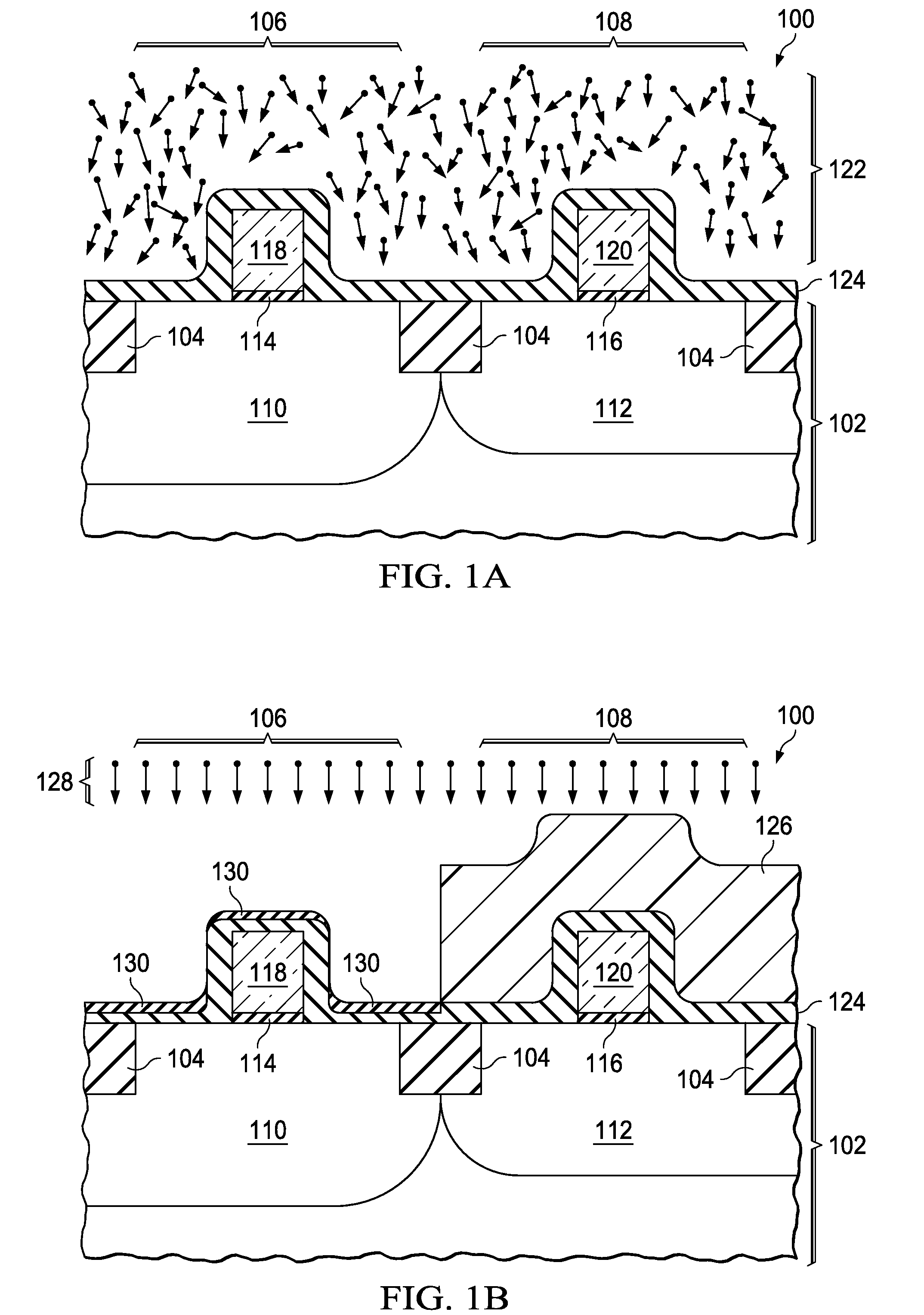
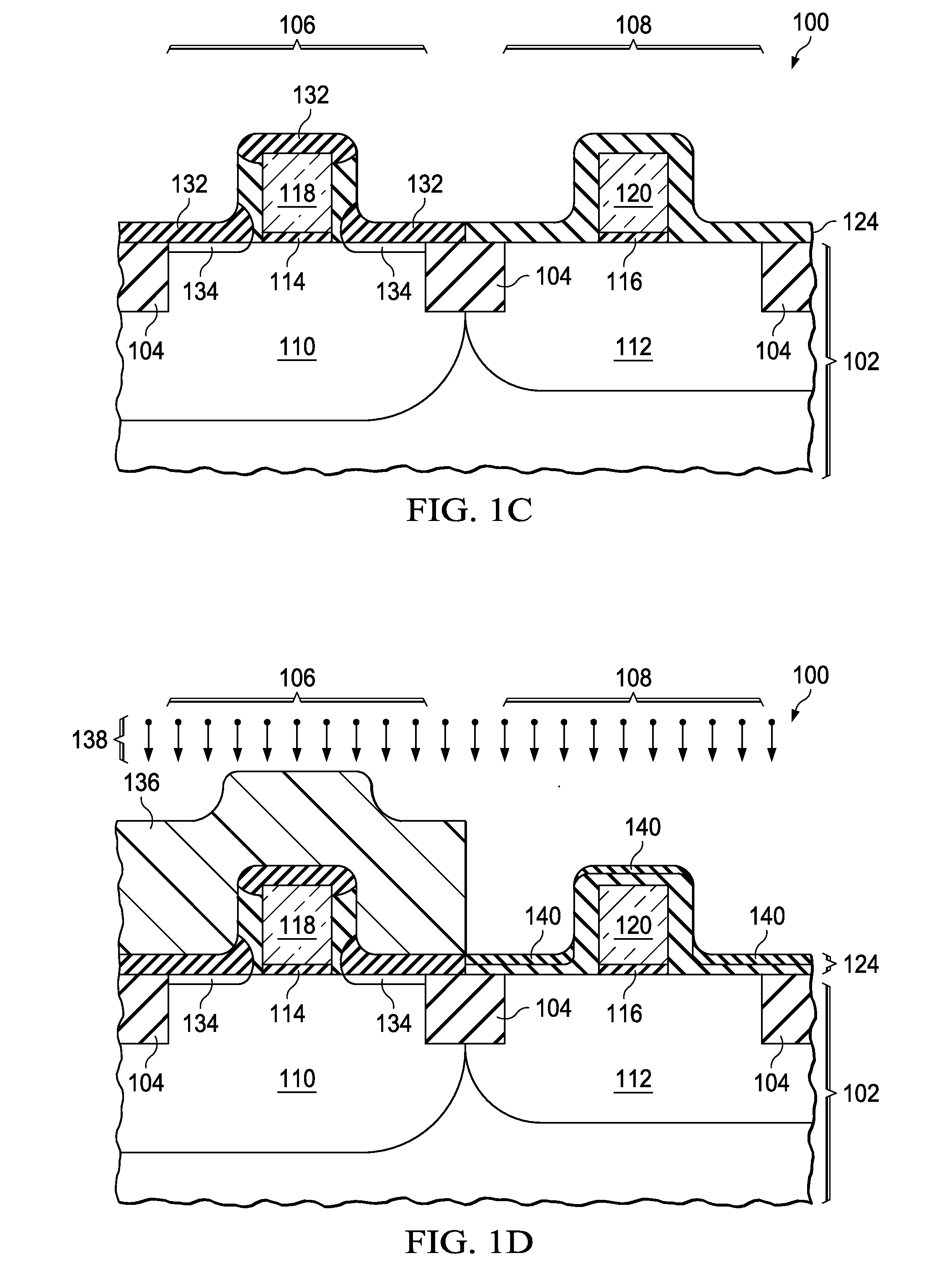
[0008]The present invention is described with reference to the attached figures, wherein like reference numerals are used throughout the figures to designate similar or equivalent elements. The figures are not drawn to scale and they are provided merely to illustrate the invention. Several aspects of the invention are described below with reference to example applications for illustration. It should be understood that numerous specific details, relationships, and methods are set forth to provide a full understanding of the invention. One skilled in the relevant art, however, will readily recognize that the invention can be practiced without one or more of the specific details or with other methods. In other instances, well-known structures or operations are not shown in detail to avoid obscuring the invention. The present invention is not limited by the illustrated ordering of acts or events, as some acts may occur in different orders and / or concurrently with other acts or events. F...


PUM


Abstract

A process for forming diffused region less than 20 nanometers deep with an average doping dose above 1014 cm−2 in an IC substrate, particularly LDD region in an MOS transistor, is disclosed. Dopants are implanted into a source dielectric layer using gas cluster ion beam (GCIB) implantation, molecular ion implantation or atomic ion implantation resulting in negligible damage in the IC substrate. A spike anneal or a laser anneal diffuses the implanted dopants into the IC substrate. The inventive process may also be applied to forming source and drain (S/D) regions. One source dielectric layer may be used for forming both NLDD and PLDD regions.

Description

FIELD OF THE INVENTION[0001]This invention relates to the field of integrated circuits. More particularly, this invention relates to methods to form shallow junctions in integrated circuits.BACKGROUND OF THE INVENTION[0002]It is well known that transistors in advanced integrated circuits (ICs) are shrinking with each new fabrication technology node, as articulated by Moore's Law. For example, at the 32 nanometer technology node, it is desired to form doped regions in transistors such as source and drain extensions which are less than 10 nanometers deep with average doping densities above 1021 cm−3. Formation of heavily doped shallow regions is problematic because anneals sufficient to repair damage to the IC substrate cause dopants to diffuse deeper than desired.SUMMARY OF THE INVENTION[0003]This Summary is provided to comply with 37 C.F.R. §1.73, requiring a summary of the invention briefly indicating the nature and substance of the invention. It is submitted with the understanding...

Claims


Application Information

Patent Timeline
IPC IPC(8): H01L21/336
CPCH01L21/2251H01L21/2255H01L21/26566H01L21/823807H01L29/7833H01L21/823842H01L21/84H01L29/6659H01L21/823814
Inventor JAIN, AMITABH
Owner TEXAS INSTR INC
Why Eureka
Try Eureka