Cooling facility for an electronic component

Inactive Publication Date: 2009-02-26
TEKTRONIX INC
View PDF14 Cites 5 Cited by
  • Summary
  • Abstract
  • Description
  • Claims
  • Application Information

AI Technical Summary

Benefits of technology

[0008]The present invention provides an improved cooling facility for an electronic component, and overcomes the above-mentioned disadvantages and drawbacks of the prior art. As such, the general purpose of the present invention, which will be described subsequently in greater detail, is to provide an improved cooling facility for an electronic component that has all the advantages of the prior art mentioned above.
[0009]To attain this, the preferred embodiment of the present invention essentially comprises a body defining a coolant passage including an inlet and an outlet, a pumping chamber with a variable volume changeable from a greater volume to a lesser volume in fluid communication with the inlet and the outlet, and a flow restriction facility in fluid communication with the inlet and the outlet.

Problems solved by technology

Failure to properly cool such electrical components can result in component malfunction, requiring thousands of dollars to be spent in their replacement and / or repair.
Unfortunately, these devices become less practical and less common as their physical size requirements are decreased to the order of 100 mm3 (cubic millimeters).
However, as the electrical components to be cooled become smaller and smaller, or as the volume of the enclosure surrounding the electrical components to be cooled decreases, one finds that off-the-shelf cooling devices become unsuitable for use because of their relatively large size.
Prior art diaphragm pumps have not heretofore been used to pump fluids for cooling applications or to pump gases.

Method used


Image

  • Cooling facility for an electronic component
  • Cooling facility for an electronic component
  • Cooling facility for an electronic component

Examples


Embodiment Construction

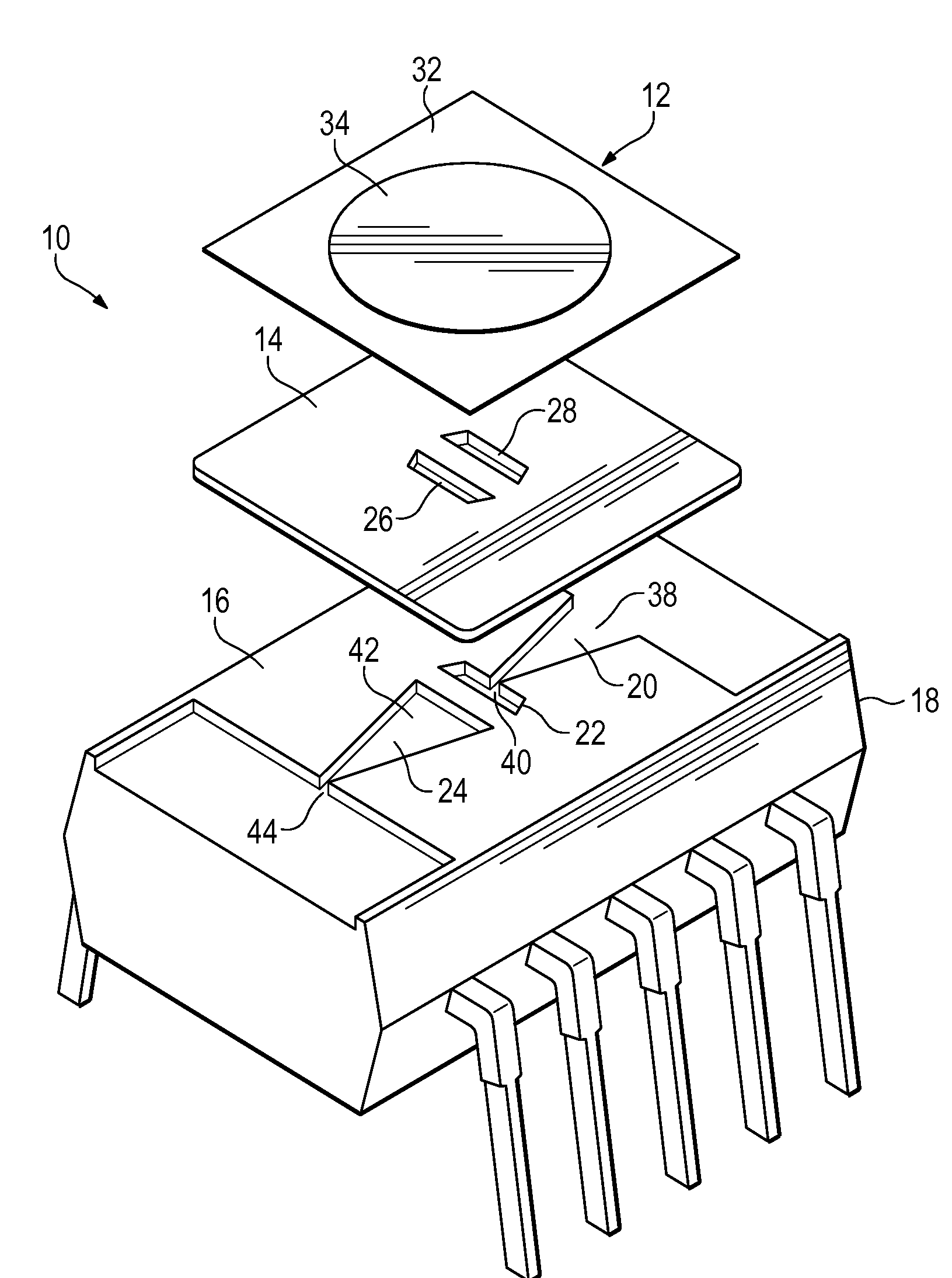
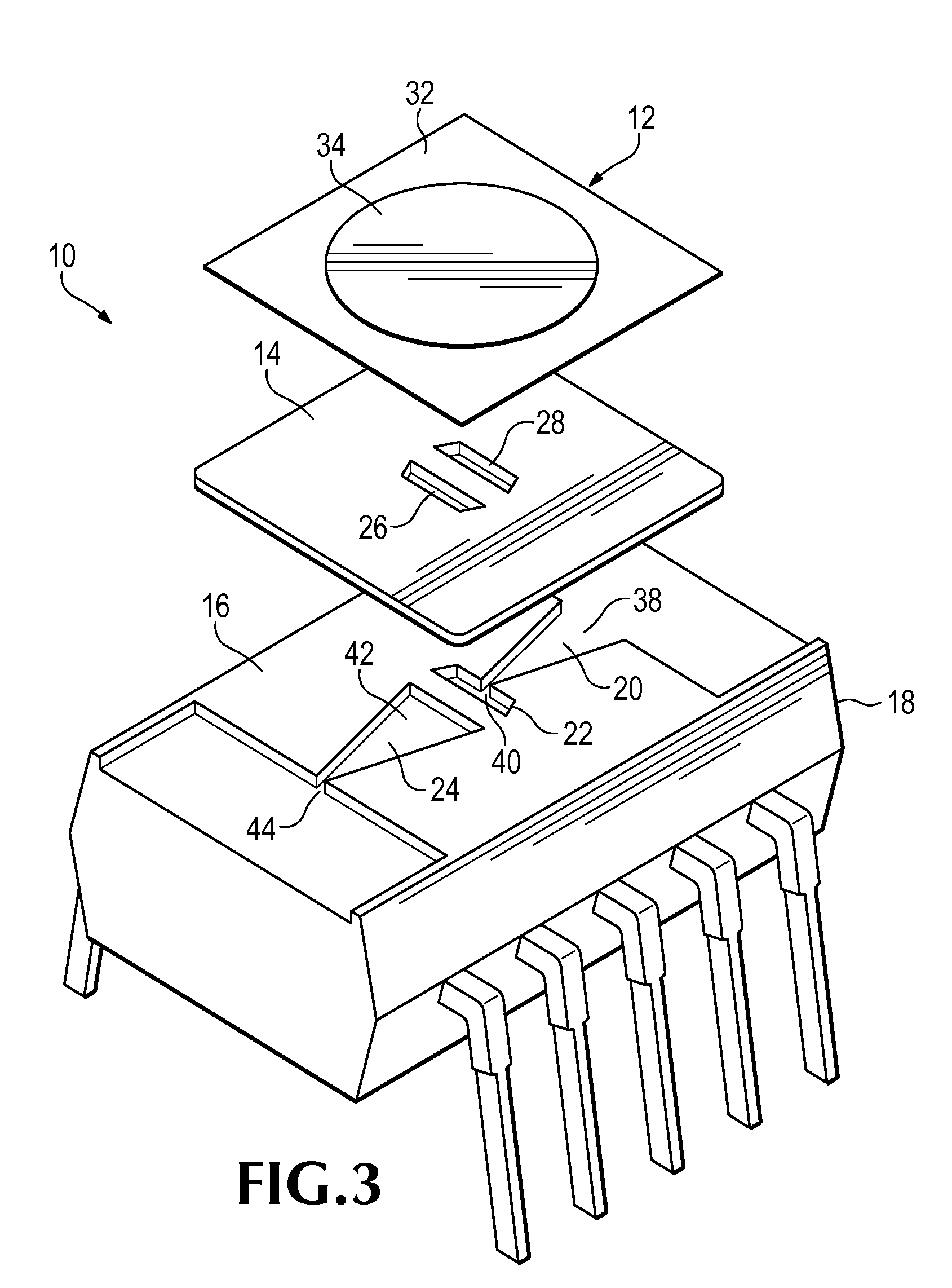
[0018]A preferred embodiment of the cooling facility for an electronic component of the present invention is shown and generally designated by the reference numeral 10.

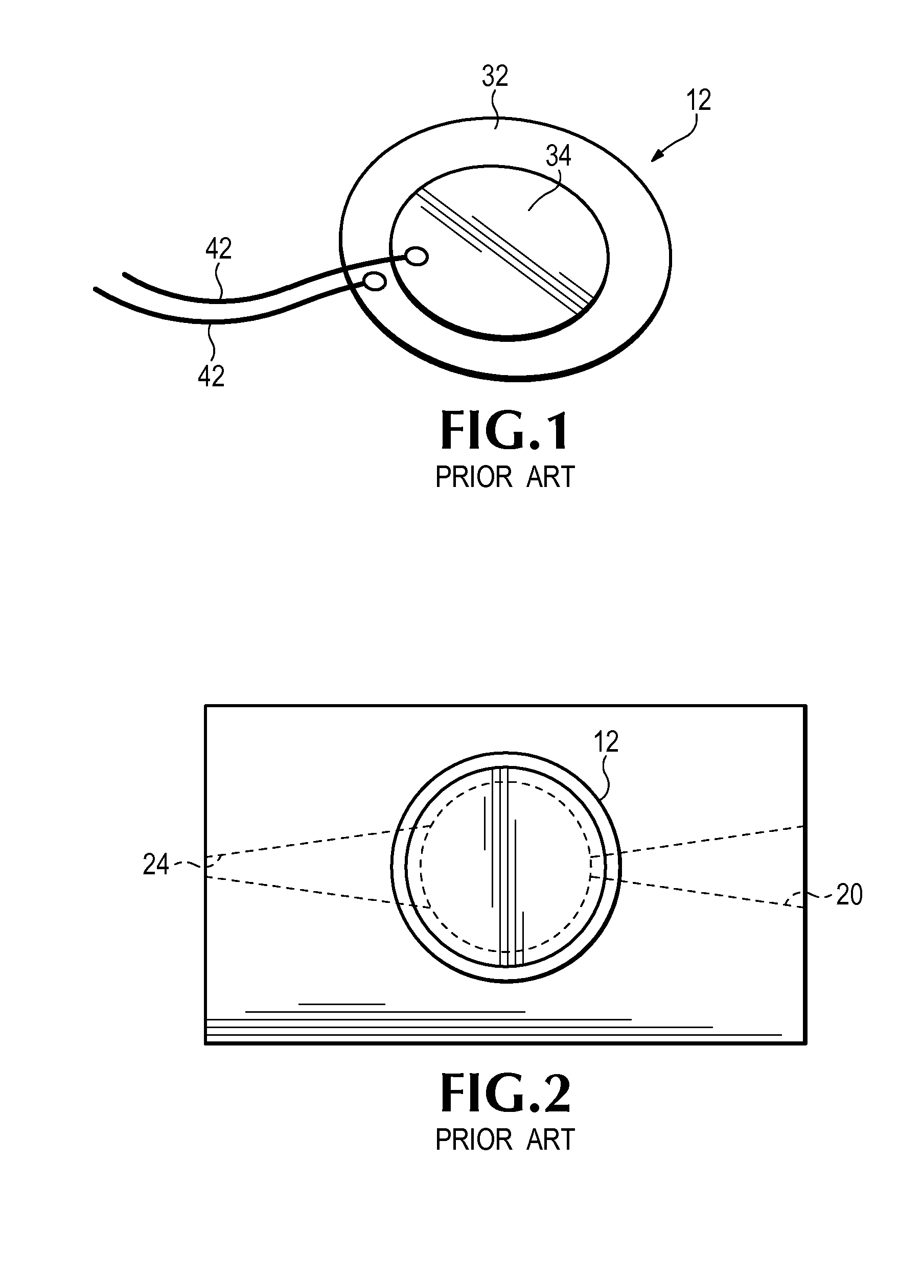
[0019]FIG. 1 illustrates a piezoelectric bending element 12 suitable for use with the current invention known as the CEB-44D06 Piezoelectric Buzzer element manufactured by CUI Inc. of Tualatin, Oreg. More particularly, piezoelectric bending element 12 has a nickel alloy piezoelectric disc backing plate 32 with a circular patch of Lead Zirconate Titanate (PZT) crystal 34 affixed to its center. An electrical potential is created between the piezoelectric disc backing plate 32 and the PZT crystal 34 using wires 42. If the electrical potential is switched at the appropriate rate, the piezoelectric bending element 12 will vibrate, acting as a diaphragm. Piezoelectric disc backing plates 32 are often used to modify the resonant frequency of the PZT crystal 34 as well as to stabilize the brittle PZT crystal 34 and provide a ...


PUM

PropertyMeasurementUnit
Temperatureaaaaaaaaaa
Lengthaaaaaaaaaa
Flow rateaaaaaaaaaa

Abstract

Cooling facilities for an electronic component provide a cooling device that occupies a small volume, requires only a relatively low operating voltage, and operates in any orientation. The cooling facility consists of a body defining a coolant passage including an inlet and an outlet, a pumping chamber with a variable volume changeable from a greater volume to a lesser volume in fluid communication with the inlet and the outlet, and a flow restriction facility in fluid communication with the inlet and the outlet. The flow restriction facility provides limited flow resistance to coolant flow in a first direction from the inlet to the outlet and provides increased resistance to coolant flow in the opposite direction from the outlet to the inlet. Therefore, repeated reciprocation of the pumping chamber between a greater volume and a lesser volume generates a net fluid flow from the inlet to the outlet.

Description

CLAIM FOR PRIORITY[0001]The subject application claims priority from U.S. Provisional Patent Application Ser. No. 60 / 957,153 entitled, APPARATUS FOR SMALL VOLUME SPOT COOLING APPLICATIONS, (Staley) filed on 21 Aug. 2007, and incorporated herein in its entirety.FIELD OF THE INVENTION[0002]The present invention relates to a cooling facility for an electronic component for use in connection with moving a fluid such as water or air. The cooling facility for an electronic component has particular utility in connection with providing a cooling device that occupies a small volume, requires only a relatively low operating voltage, and operates in any orientation.BACKGROUND OF THE INVENTION[0003]Cooling facilities for an electronic component are desirable for providing a cooling device that occupies a small volume, requires only a relatively low operating voltage, and operates in any orientation. Modern semiconductors tend to generate greater heat than ever when carrying out their respective...

Claims


Application Information

Patent Timeline
IPC IPC(8): F28D15/00B21D53/02
CPCH01L23/467H01L2924/0002Y10T29/4935H01L2924/00
Inventor STALEY, THOMAS
Owner TEKTRONIX INC
Why Eureka
Try Eureka