
Fin-tube heat exchanger

a heat exchanger and tube heat exchange technology, applied in the field of tube heat exchangers, can solve the problems of certain limitations of heat transfer coefficient improvement, and achieve the effect of improving heat transfer coefficient and convenient manufactur

Inactive Publication Date: 2009-02-26
PANASONIC INTELLECTUAL PROPERTY MANAGEMENT CO LTD
View PDF18 Cites 12 Cited by
  • Summary
  • Abstract
  • Description
  • Claims
  • Application Information

AI Technical Summary

Benefits of technology

[0006]In the slit fin 101, however, the cross-sectional shape of the slit portions 102 is rectangular. Therefore, although it can obtain the effect of dividing the thermal boundary layer BL that develops from the front edge 101a, it has been unable to achieve further advantageous effects. Thus, even if some optimization in the dimensions of the slit portions 102, for example, is made, there have been certain limitations to improvements in heat transfer coefficient.
[0007]The present invention has been accomplished in view of the foregoing circumstances, and it is an object of the invention to provide a fin-tube heat exchanger that can achieve an improvement in heat transfer coefficient over prior art and at the same time maintains easy manufacturability.
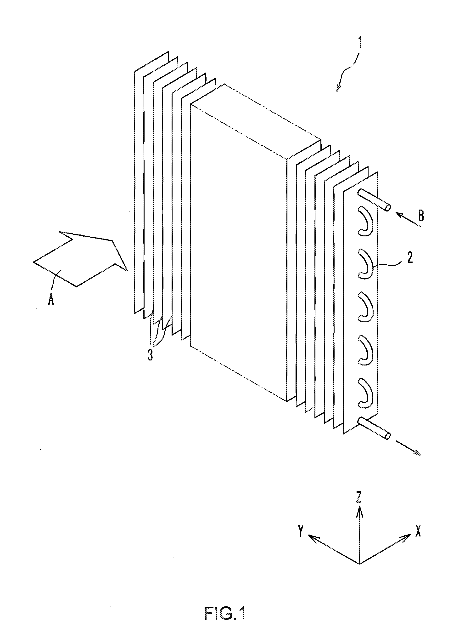
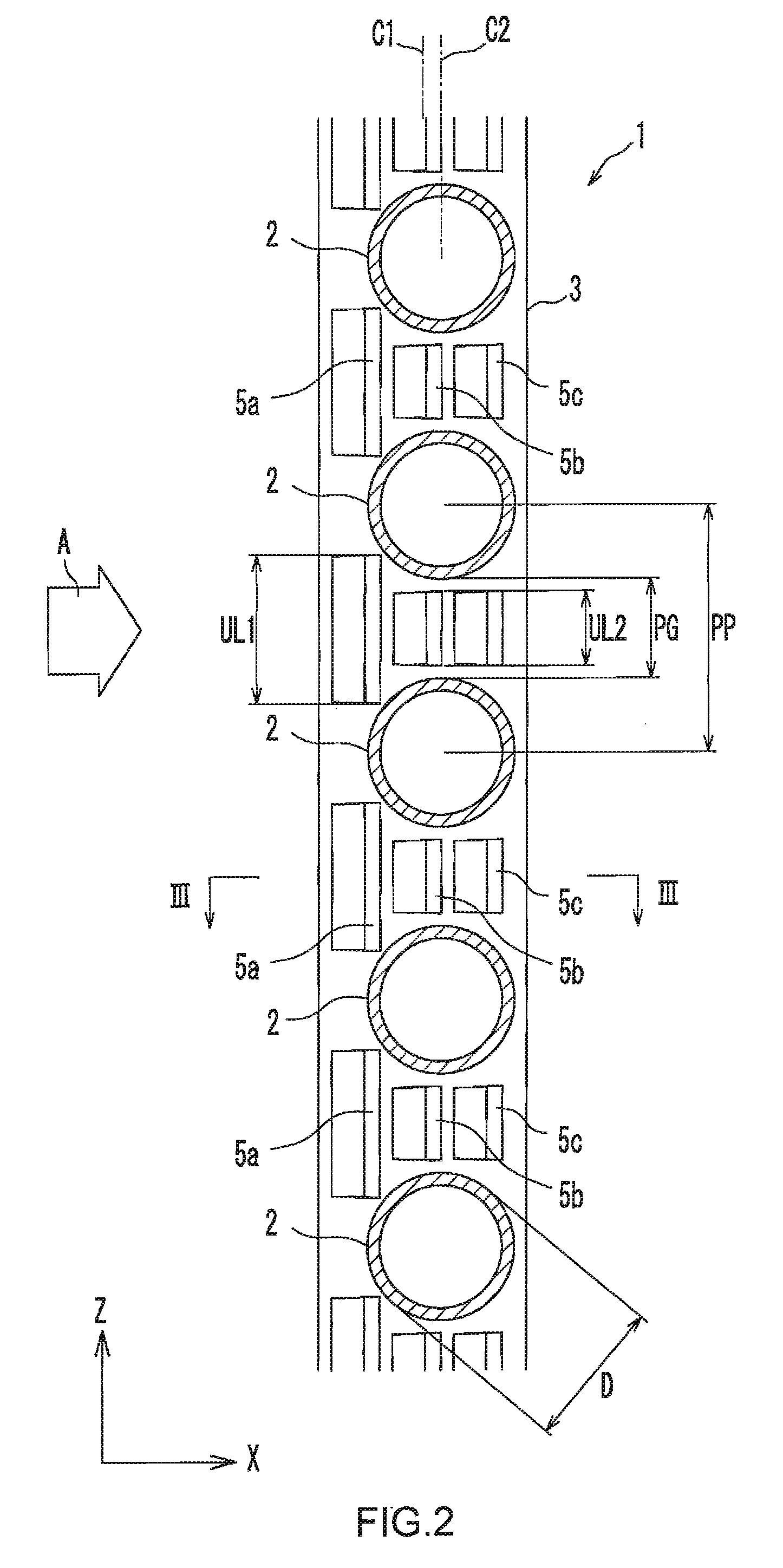
[0008]A fin-tube heat exchanger according to the present invention includes: a plurality of fins spaced apart from and parallel to each other; and a plurality of heat transfer tubes penetrating the fins, the fin-tube heat exchanger being for exchanging heat between a first fluid flowing on a surface side of the fins and a second fluid flowing inside the heat transfer tubes, wherein a cut-and-raised portion is formed in each of the fins, the cut-and-raised portion being formed by cutting and raising a portion of the each of the fins so as to be turned over from an upstream side to a downstream side of a flow direction of the first fluid, and having a horizontal cross-sectional shape that is curved or bent so as to taper toward the upstream side.
[0009]The horizontal cross sectional shape of the cut-and-raised portion may be a semicircular shape. Alternatively, the horizontal cross sectional shape of the cut-and-raised portion may be a semielliptic shape. Alternatively, the horizontal cross sectional shape of the cut-and-raised portion may be a semielliptic shape that is slender toward the upstream side. In addition, the horizontal cross sectional shape of the cut-and-raised portion may be a wedge shape.
[0010]A plurality of the cut-and-raised portions may be provided along the flow direction of the first fluid, and the cut-and-raised portions that are adjacent to each other along the flow direction are cut and raised in alternately opposite directions from each of the fins.
[0011]A raised height of the cut-and-raised portion may be equal to or less than ½ of a fin pitch.

Problems solved by technology

Thus, even if some optimization in the dimensions of the slit portions 102, for example, is made, there have been certain limitations to improvements in heat transfer coefficient.

Method used


Image

  • Fin-tube heat exchanger
  • Fin-tube heat exchanger
  • Fin-tube heat exchanger

Examples


embodiment 1

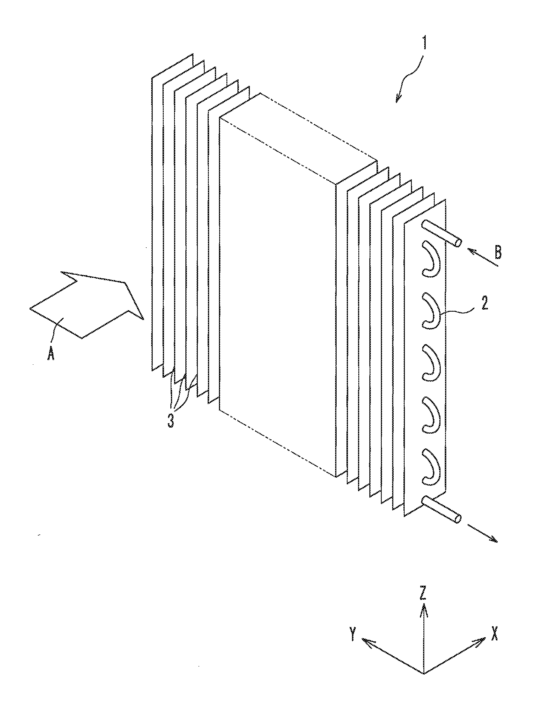
[0037]As illustrated in FIG. 1, a fin-tube heat exchanger 1 according to the embodiment has a plurality of fins 3 arranged parallel to each other with a predetermined gap, and a plurality of heat transfer tubes 2 penetrating these fins 3. The heat exchanger 1 is for exchanging heat between a fluid flowing inside the heat transfer tubes 2 and a fluid flowing on the surface side of the fins 3 (the surfaces of the fins 3 when the outer surfaces of the heat transfer tubes 2 are not exposed, or the surfaces of the fins 3 and the heat transfer tubes 2 when the outer surfaces of the heat transfer tubes 2 are exposed). In the present embodiment, air A flows on the surface side of the fins 3, and refrigerant B flows inside the heat transfer tubes 2. It should be noted that the fluid that flows inside the heat transfer tubes 2 and the fluid that flows on the surface side of the fins 3 are not particularly limited. Each of the fluids may be either a gas or a liquid.

[0038]The fins 3 are formed ...

embodiment 2

[0067]In Embodiment 1, the cut-and-raised portions 5a-5c are formed to have a horizontal cross-sectional shape in a semicircular shape. However, the horizontal cross-sectional shape of the cut-and-raised portions 5a-5c is not limited to the semicircular shape. As illustrated in FIG. 7, a fin-tube the heat exchanger 1 according to Embodiment 2 is such that the horizontal cross-sectional shape of the cut-and-raised portions 5a-5c is formed in a semielliptic shape.

[0068]Specifically, each of the fins 3 of the heat exchanger 1 according to Embodiment 2 has cut-and-raised portions 5a-5c formed by cutting and raising portions of the fin 3 so as to be turned over from the upstream side toward the downstream side. The cut-and-raised portions 5a-5c are curved so that the horizontal cross-sectional shape tapers toward the upstream side, and are formed in a semielliptic shape. The rest of the configurations are the same as those in Embodiment 1 and the description thereof will be omitted.

[0069...

embodiment 3

[0073]As illustrated in FIG. 9, a fin-tube the heat exchanger 1 according to Embodiment 3 is such that the horizontal cross-sectional shape of the cut-and-raised portions 5a-5c is formed in a wedge shape.

[0074]Specifically, each of the fins 3 of the heat exchanger 1 according to Embodiment 3 has cut-and-raised portions 5a-5c formed by cutting and raising portions of the fin 3 so as to be turned over from the upstream side toward the downstream side. The cut-and-raised portions 5a-5c are curved so that the horizontal cross-sectional shape tapers toward the upstream side, and are formed in a wedge shape. It should be noted that the term “wedge shape” refers to a shape such as to continuously spread from the front edge to the rear edge. The rest of the configurations are the same as those in Embodiment 1 and the description thereof will be omitted.

[0075]In the present embodiment as well, the horizontal cross-sectional shape of the cut-and-raised portions 5a-5c is formed to taper toward...


PUM


Abstract

A fin-tube heat exchanger has a plurality of fins (3) arranged parallel to and spaced from each other at a predetermined gap, and a plurality of heat transfer tubes (2) penetrating the fins (3). In each of the fins (3), a first cut-and-raised portion (5a), a second cut-and-raised portion (5b), and a third cut-and-raised portion (5c) are formed in that order by cutting and raising a portion of the each of the fins so as to turn it over from an upstream side to a downstream side. The horizontal cross-sectional shape of each of the first cut-and-raised portion (5a), the second cut-and-raised portion (5b), and the third cut-and-raised portion (5c) is formed in a semicircular shape and curved so as to taper toward the upstream side.

Description

TECHNICAL FIELD[0001]The present invention relates to fin-tube heat exchangers.BACKGROUND ART[0002]Conventionally, fin-tube heat exchangers commonly have been used for various apparatuses such as air conditioners, freezer-refrigerators, and dehumidifiers. A fin-tube heat exchanger is composed of a plurality of fins that are arranged parallel to each other and spaced with a predetermined gap, and heat transfer tubes that extend through these fins.[0003]Known fin-tube heat exchangers include ones with various ingenious fin shape designs so as to enhance heat transfer. For example, a heat exchanger in which a large number of pins are provided on a fin surface has been known. In this heat exchanger, the flow on the fin surface is stirred by these pins, so heat exchange is thereby enhanced.[0004]However, providing the pins, which are different members from the fin, additionally on the fin complicates the manufacturing process. In view of this, a heat exchanger in which the fin shape is m...

Claims


Application Information

Patent Timeline
Patent Type & Authority Applications(United States)
IPC IPC(8): F28D1/04
CPCF28F1/325F28D1/0477
Inventor KOMORI, KOUOGAWA, OSAMUHAYASHI, HIROKI
Owner PANASONIC INTELLECTUAL PROPERTY MANAGEMENT CO LTD
Learn More