In-wall mount

a flat panel display and mount technology, applied in the direction of curtain suspension devices, furniture parts, machine supports, etc., can solve the problems of limiting the position of the in-wall enclosure, and affecting the appearance of the display

Active Publication Date: 2009-02-26
LEGRAND AV INC
View PDF99 Cites 99 Cited by
  • Summary
  • Abstract
  • Description
  • Claims
  • Application Information

AI Technical Summary

Benefits of technology

[0014]The centering in-wall mount of the present invention substantially meets the aforementioned needs of the industry. The centering in-wall mount eliminates the need for remodeling wall framing when mounting a r

Problems solved by technology

Such positionable mounts typically are thicker in depth and result in the back of the display being mounted further from the wall surface.
A limitation of the present in-wall recessed mounts is that they are typically constrained to being centered between adjacent studs.
Such framing can be an expensive modification that is both time consuming and messy in an existing structure.
A disadvantage of these prior solutions, however, is that the in-wall enclosure must be attached to the wall studs in order to support the weight of the display, and thus the position of the in-wall enclosure is typically limited by the location of the wall studs.
This results in a large in-wall enclosure that may be unsightly.
In ad

Method used


Image

  • In-wall mount
  • In-wall mount
  • In-wall mount

Examples


Embodiment Construction

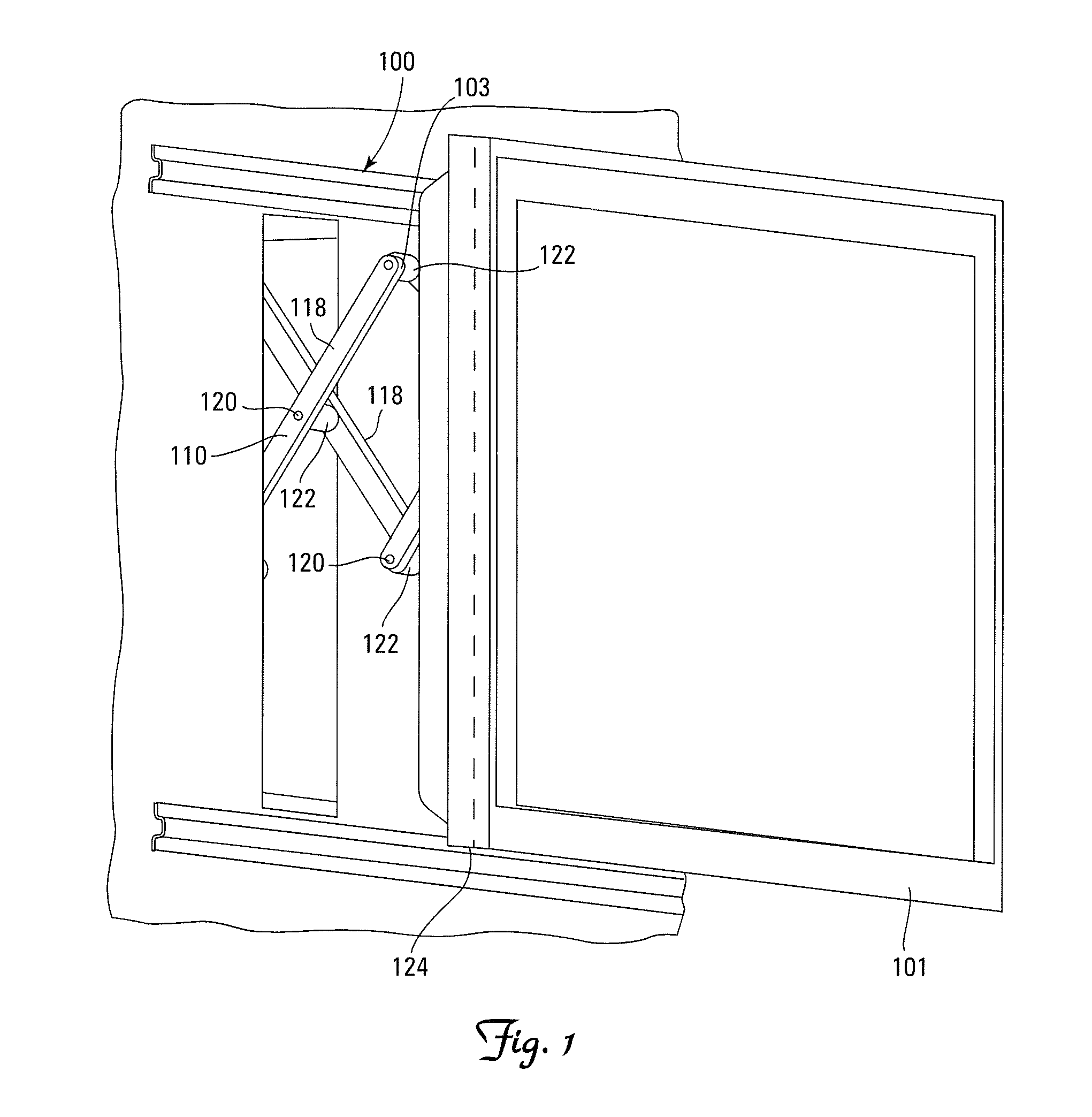
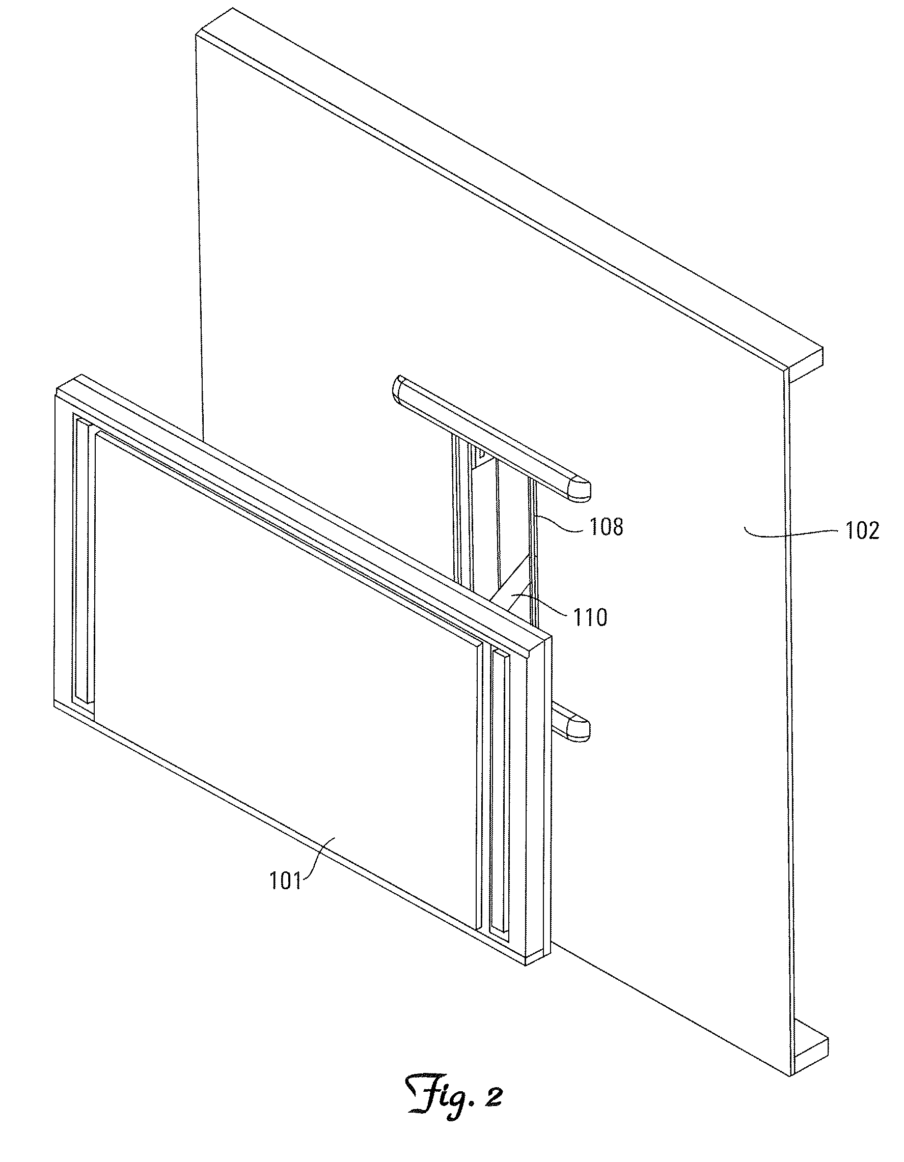
[0044]A typical wall 10 is depicted in the figures. Wall 10 includes framing comprising a sill plate 12, an opposed parallel header 14, and studs 16. The header 14 is supported on the plurality of generally parallel vertical studs 16 that are mounted on top of the sill plate 12 and extend upward to the header 14. Dry wall sheeting 18 is affixed to the wall framing to complete the wall structure. A rectangular aperture 19 is defined in the dry wall 19 between two adjacent studs 16. The aperture 19 is formed just slightly bigger than the exterior dimensions of the mount 20.

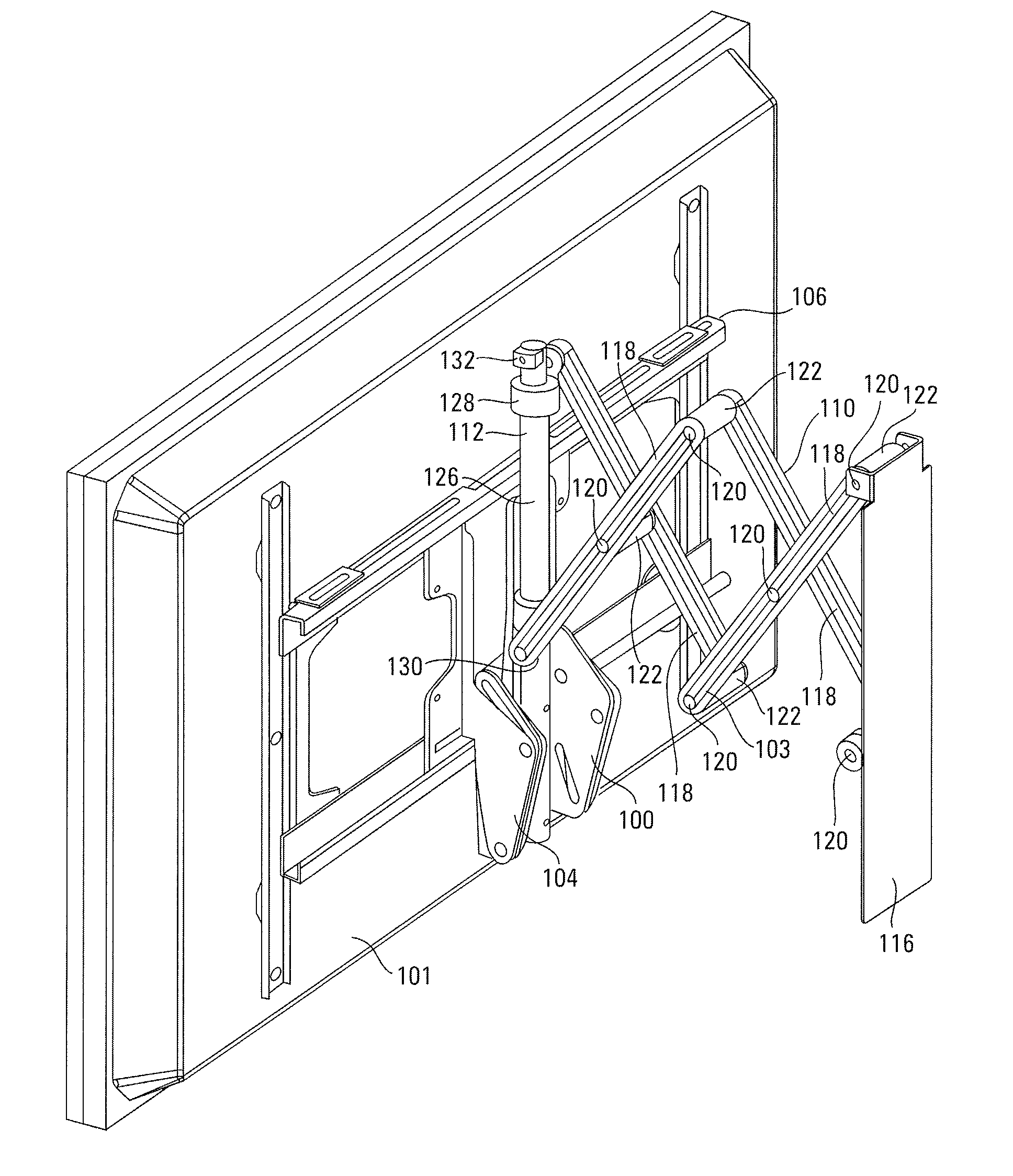
[0045]The centering in-wall mount 20 of the present invention includes two major subcomponents: mount box 21 and mount base 28. The mount box 21 is preferably made of relatively heavy structural material in order to support the cantilevered weight of a flat panel display and is fixedly secured to the adjacent studs 16 on either side of the aperture 19. The mount box 21 has a top 41 and an opposed bottom 42 that are ...


PUM


Abstract

An in-wall mount for supporting an electronic display from a wall. The in-wall mount includes a wall interface structure, a display interface structure, and an extensible arm assembly. The display interface structure is selectively outwardly shiftable relative to the wall interface structure between a first position wherein the display interface structure is proximate the wall interface structure and a second position wherein the display interface structure is spaced apart from the wall interface structure, the display interface structure rising vertically relative to the wall interface structure as the display interface structure is shifted from the first position to the second position.

Description

RELATED APPLICATIONS[0001]This application is a continuation under 35 U.S.C. § 120 of International Application PCT / US2008 / 000130, filed Jan. 4, 2008, entitled IN-WALL MOUNT, which claims the benefit of U.S. Provisional Application No. 60 / 883,652, filed Jan. 5, 2007, and U.S. Provisional Application No. 60 / 957,937, filed Aug. 24, 2007, and this application further claims the benefit of U.S. Provisional Application No. 60 / 957,941, filed Aug. 24, 2007, all the recited applications being incorporated herein in their entirety by reference.FIELD OF THE INVENTION[0002]The present invention relates to mounts for flat panel displays, and more particularly to in-wall mounts for flat panel displays.BACKGROUND OF THE INVENTION[0003]Flat panel electronic displays have become very popular due to their compact size, desirable aesthetics, and superior performance. The inherent form factor and weight advantages of these displays have made large screen sizes economically and practically feasible, le...

Claims


Application Information

Patent Timeline
IPC IPC(8): A47B96/06
CPCF16M11/10F16M11/12F16M11/2014F16M2200/061F16M11/24F16M11/38F16M13/02F16M11/2092Y10S248/917
Inventor DITTMER, JAY
Owner LEGRAND AV INC
Why Eureka
Try Eureka