Programmable Light Display

a technology of led light fixtures and light displays, applied in the field of light fixtures, can solve the problems of relatively inefficient systems, unreliable, and led light fixtures may suffer from inefficient light dispersion characteristics, and achieve the effect of reducing impedan

Active Publication Date: 2009-02-26
SONOMA CIRCUITS
View PDF26 Cites 90 Cited by
  • Summary
  • Abstract
  • Description
  • Claims
  • Application Information

AI Technical Summary

Benefits of technology

[0018]In yet another embodiment, the light assembly may employ a protocol in which a first fixture in a series functions as a master unit, unless the first fixture is defective, in which event a next fixture in the series functions as a master unit. Voltage applied to a master unit may cause it to function as a marker light. The act of grounding may cause the first fixture in a series of fixtures to function as the master unit. Further, the master unit may cause its corresponding slave units to function in an alternating flash pattern in which every other fixture is on for a predetermined period of time, and then off for a predetermined period of time. The input current transmitted to the lamps may be limited to a predetermined, substantially fixed amount, thereby decreasing impedance needed for external loads to be treated as a grounding of the incoming control lead.
[0019]In another embodiment, a current source for one the light fixtures may be caused to operate in a non-linear range for relatively low level loads in the range of 9-32 volts, for example, providing a non-linear voltage drop relative to the current on the incoming control lead and enabling the light assembly to function with an impedance on the incoming control lead that would be caused by submerging the control lead under tap water (rain or snow melt may also be used).
[0027]A system including one or more groups of lighting fixtures, with each of the one or more groups including fixtures connected in series, also forms part of the present invention. This system may include a microcontroller, and a bypass circuit configured to pass on operating instructions to successive fixtures within a group in the event of an error in the operation of the microcontroller. An illuminator array including one or more of the groups of lighting fixtures, such as lamps, may be employed. One or more array drives may also be used for operating the illuminator array. The array drives may be DC-to-DC converter, providing a generally constant current source for each of the lamps in the series, and providing reverse polarity protection. A transceiver may be configured to receive operating control signals and to transmit control signals to succeeding fixtures within a group. The illumination provided by the illuminator array preferably remains generally constant over a given DC voltage range, such as (but not limited to) a DC voltage range of between about 8 and 32 volts.

Problems solved by technology

But such systems are relatively inefficient and unreliable when compared to light emitting diodes (LEDs), which have an operating life of up to 100,000 hours before significant degradation.
Further, LED light fixtures may suffer from inefficient light dispersion characteristics.

Method used


Image

  • Programmable Light Display
  • Programmable Light Display
  • Programmable Light Display

Examples


Embodiment Construction

[0059]Set forth below is a description of what are believed to be the preferred embodiments and / or best examples of the invention claimed. Future and present alternatives and modifications to the preferred embodiments are contemplated. Any alternatives or modifications which make insubstantial changes in function, in purpose, in structure, or in result are intended to be covered by the claims of this patent.

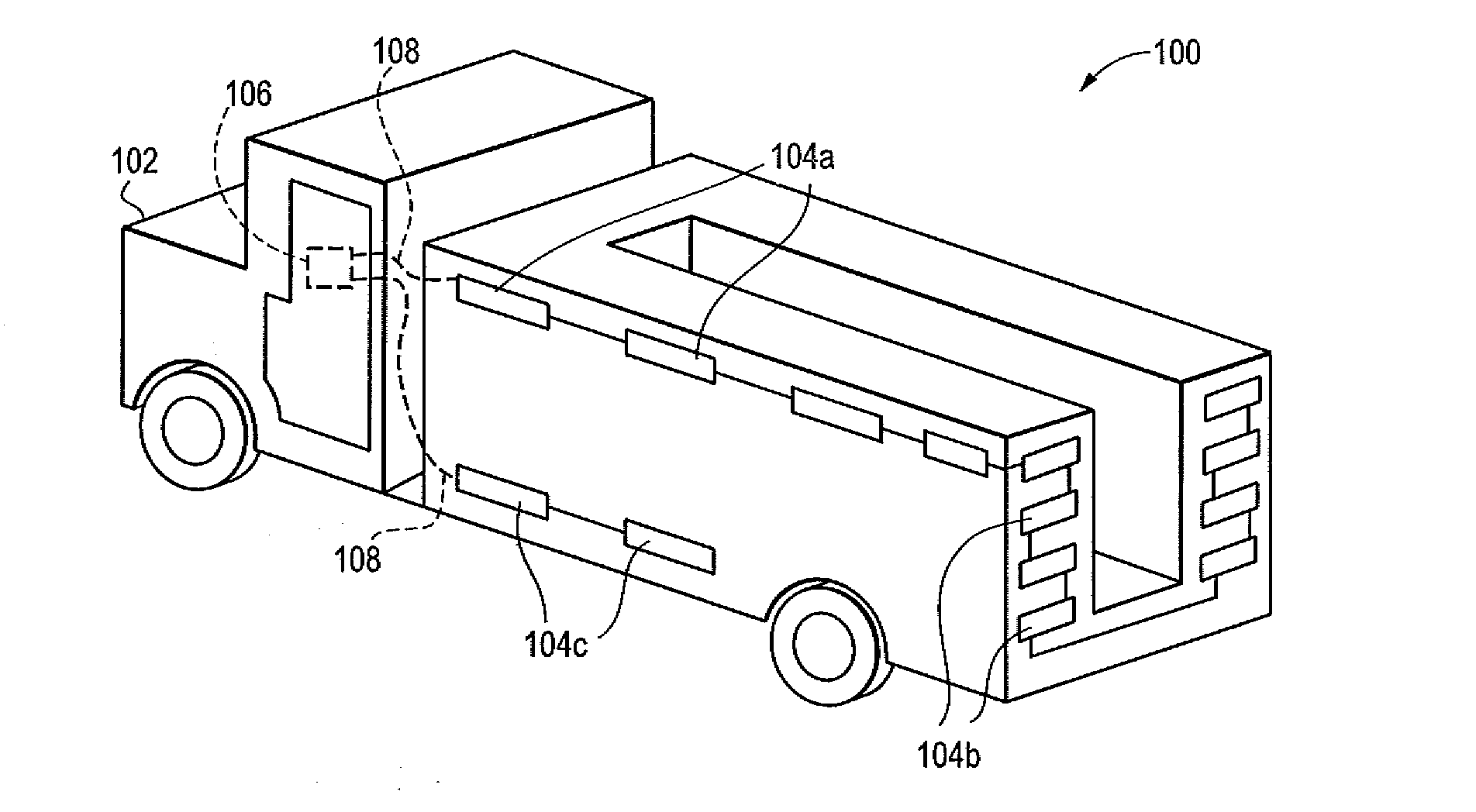
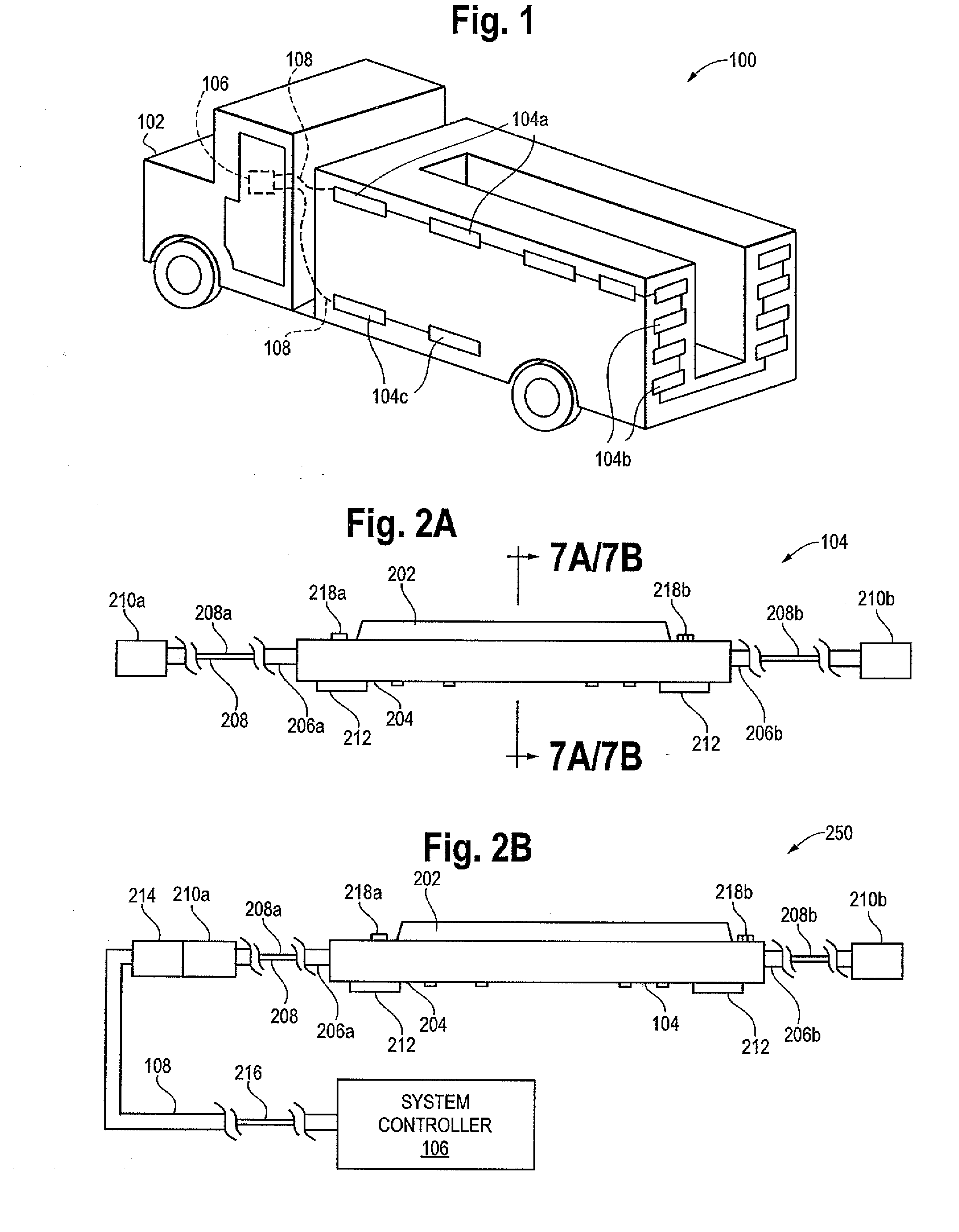
[0060]Referring initially to FIG. 1, a representative view 100 of a vehicle is provided. In the representative view 100, a truck 102, employing an embodiment of the invention is shown that may include a system controller 106 and a plurality of light fixtures 104a, 104b, and 104c. System controller 106 may provide control wiring to light fixtures 104 via system cable(s) 108. In another embodiment, system controller 106 may be a wireless unit in communication with fixtures 104 configured to receive and transmit data via wireless communication systems.

[0061]As described in greater d...


PUM


Abstract

Programmable light assemblies that may function in various operating modes, such as to function as marker lights and / or emergency lights, or have other functions, are disclosed. The protocol and architecture of the light assemblies enables the associated light fixtures to provide a constant current output despite the presence of substantially large voltage ranges, and even when submerged in water. Alternative embodiments of the programmable light assemblies of the invention provide many other features as described herein.

Description

FIELD OF THE INVENTION[0001]The present invention relates generally to lighting fixtures that may be operated in a coordinated manner. More specifically, the invention relates to programmable LED light fixtures that may be used for vehicle lighting and other applications, as standalone units, and in a coordinated series of fixtures.BACKGROUND OF THE INVENTION[0002]Vehicle marker lights have long been used to signal, for example, emergency (e.g., tow trucks and police or fire vehicles) and maintenance vehicles (e.g., street sweepers), as shown, for example, in U.S. Pat. Nos. 3,484,598, 3,692,998, 5,299,102 and 6,858,986, each of which are entirely incorporated herein by reference. Incandescent lighting systems have traditionally been used for this purpose. But such systems are relatively inefficient and unreliable when compared to light emitting diodes (LEDs), which have an operating life of up to 100,000 hours before significant degradation. Recently, LED vehicle marker light system...

Claims


Application Information

Patent Timeline
Patent Type & Authority Applications(United States)
IPC IPC(8): H05B39/00
CPCB60Q1/2611B60Q1/32H05B37/038H05B37/0254H05B37/029H05B33/0803H05B47/18H05B47/155H05B47/235H05B47/17H05B45/32H05B45/345H05B45/3725
Inventor HICKSTED, RICHARD L.WILSON, GARYBRYAN, RAYMOND G.
Owner SONOMA CIRCUITS
Why Eureka
Try Eureka