Wide area high resolution SAR from a moving and hovering helicopter

a high-resolution, wide-area technology, applied in the direction of instruments, using reradiation, transportation and packaging, etc., can solve the problems of reducing the utility of pulses, inaccurate summing of radar returns over arrays, and inability to fully compensate for phas

Active Publication Date: 2009-02-26
RAYTHEON CO
View PDF7 Cites 22 Cited by
  • Summary
  • Abstract
  • Description
  • Claims
  • Application Information

AI Technical Summary

Benefits of technology

[0012]Above limitations of the SAR process are avoided by a hovering (stationary) or moving helicopter equipped with a radar system for acquiring a synthetic aperture image of a target. The helicopter has a radar transmitter for transmitting radar pulses for illuminating the target, and one or more rotor blades for generating lift for the helicopter. One or more radar reflectors are

Problems solved by technology

Where a non-ideal platform motion exists, having forward flight path deviations away from a rectilinear, planar path, motion compensation (INS based) of the pulses may not fully compensate for phase errors.
Consequently, the coherent summing of radar returns over an array will also be inaccurate.
The resulting phase error over the array blurs the SAR image, reducing its utility.
Autofocus is applied where the accuracy of the INS derived motion compensation phase compensation applied to each radar A/D sample is insufficient.
Another problem in the prior art is that SAR is side looking.
Without platform motion, the principles of SAR cannot be ap

Method used


Image

  • Wide area high resolution SAR from a moving and hovering helicopter
  • Wide area high resolution SAR from a moving and hovering helicopter
  • Wide area high resolution SAR from a moving and hovering helicopter

Examples


Embodiment Construction

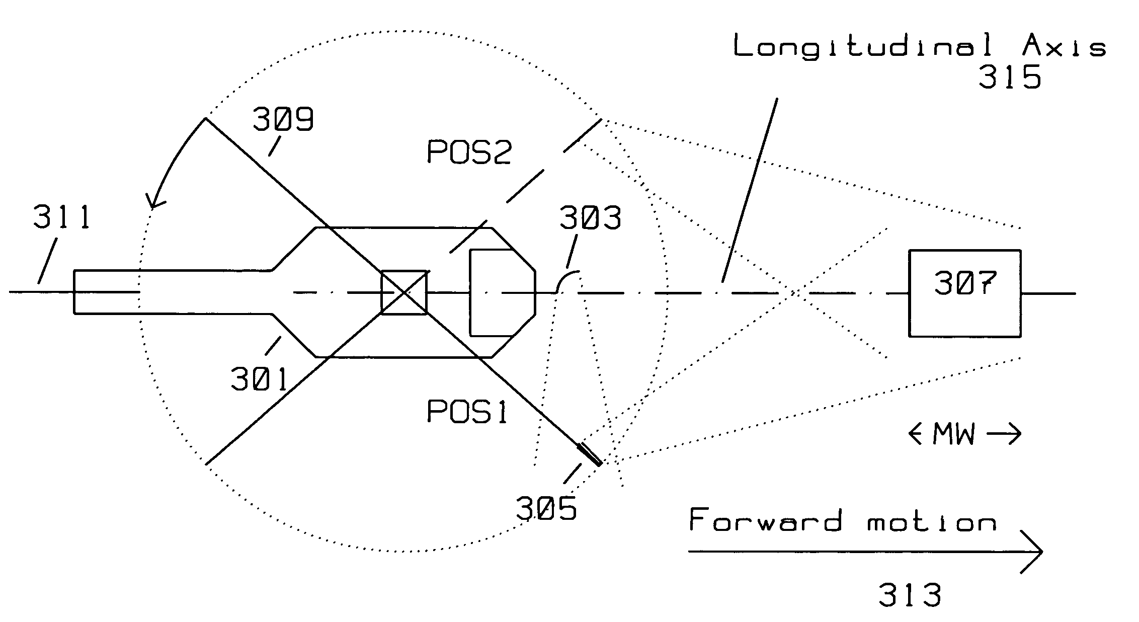
[0022]This disclosure introduces the concept of using a moving blade reflector rotatingly attached to a stationary platform to generate a forward looking SAR image. The radar return motion compensation is derived from the direct reflections off the moving, blade reflector itself, simplifying motion compensation computations. Typically, the moving blade reflector is attached to the main lift rotor blade(s) of a helicopter.

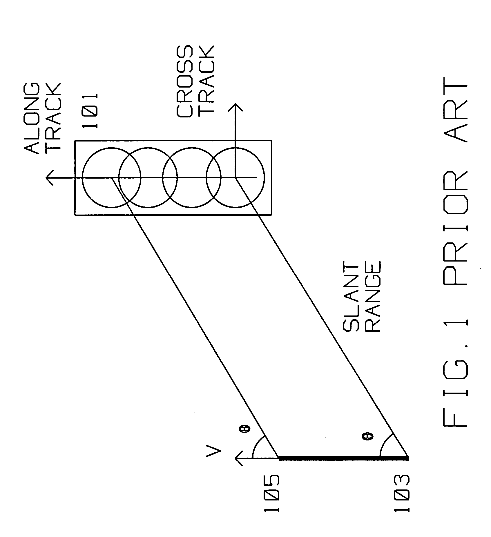
[0023]FIG. 1 shows the typical prior art geometric relationship between a moving platform carrying a radar transmitter / receiver using Synthetic Aperture (SAR) search methods imaging target 101 by said radar transmitter / receiver in a swath mode. The moving platform is initially at position 103, travels with velocity V in the direction shown to position 105. In SAR search (or swath) mode, the SAR antenna azimuth is fixed at azimuth angle θ oriented towards target 101 as the platform moves with velocity V. The moving platform moves from position 103 to position 105, wh...


PUM


Abstract

A hovering helicopter has a radar transmitter/receiver for transmitting radar pulses for illuminating a target for SAR imaging, and rotor blades for generating lift. Radar reflectors are on the rotor blades. The radar reflectors are oriented to reflect the radar pulses from the transmitter to the target as the rotor blades rotate. The radar pulses reflected by the moving reflector from the transmitter are timed to generate the synthetic aperture image using radar returns from the target. The receiver also receives blade returns directly reflected from the moving reflectors attached to the lift rotor blades. The receiver analyzes the blade returns to extract motion details of the reflectors and uses the motion details for motion compensation of target returns for SAR imaging.

Description

BACKGROUND OF THE INVENTION[0001]1. Field of Invention[0002]This disclosure is in the field of Synthetic Aperture Radar (SAR) and imaging obtained from a stationary or moving platform where platform motion is not required for SAR imaging.[0003]2. Description of the Related Art[0004]Synthetic Aperture Radar (SAR) is used for ground mapping as well as target identification. A general principle behind SAR is to coherently combine the amplitude and phase information of radar returns from a plurality of sequentially transmitted pulses. These pulses are from a relatively small antenna on a forward moving platform. As the platform moves, the information contained in the radar returns acquired at different positions is coherently combined to arrive at a SAR image. An increase in resolution of SAR, as compared to a stationary antenna of the same size, comes from the forward motion of the SAR antenna and collection of multiple returns along the path covered by the SAR antenna. The SAR image i...

Claims


Application Information

Patent Timeline
IPC IPC(8): G01S13/90B64C27/04
CPCG01S2013/9082G01S13/9035G01S7/4026G01S13/904G01S13/9082
Inventor KRIKORIAN, KAPRIEL V.ROSEN, ROBERT A.GUBALA, MICHAEL
Owner RAYTHEON CO
Why Eureka
Try Eureka