
IP Telephone System

a telephone system and telephone technology, applied in the field of ip telephone systems, can solve the problems of not being able to continuously use for a long time, and up a battery capacity quickly, and achieve the effect of reducing power consumption of communication terminals and easy switching

Active Publication Date: 2009-02-26
UNIVERSAL ENTERTAINMENT CORP
View PDF5 Cites 12 Cited by
  • Summary
  • Abstract
  • Description
  • Claims
  • Application Information

AI Technical Summary

Benefits of technology

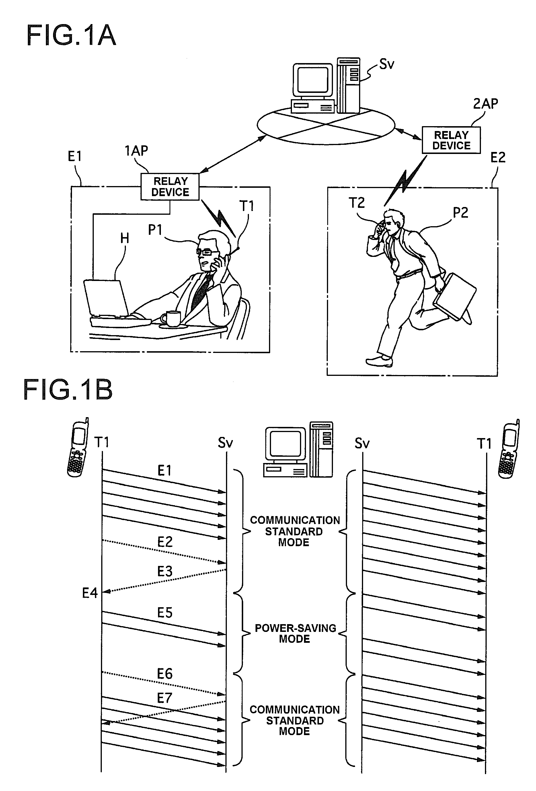
[0011]According to the first aspect of the present invention, the switching control is exercised, upon input of the predetermined command, to switch the mode between the standard communication mode and the power-saving communication mode. In this manner, for example, the process that consumes the large amount of power can be reduced, thereby reducing the battery power consumption of the communication devices. As a result, the communication device can be continuously used over a long time.
[0028]The present invention provides an IP telephone system which achieves lower power consumption of the communication terminal, thereby enabling its continuous use over a long time.

Problems solved by technology

However, the current IP telephones (communication devices) entails a problem that they cannot be continuously used over a long time.
This is because communication (telephone conversation) between the IP phones requires a process that consumes a large amount of power, thereby using up a battery capacity quickly.

Method used


Image

  • IP Telephone System
  • IP Telephone System
  • IP Telephone System

Examples


first embodiment

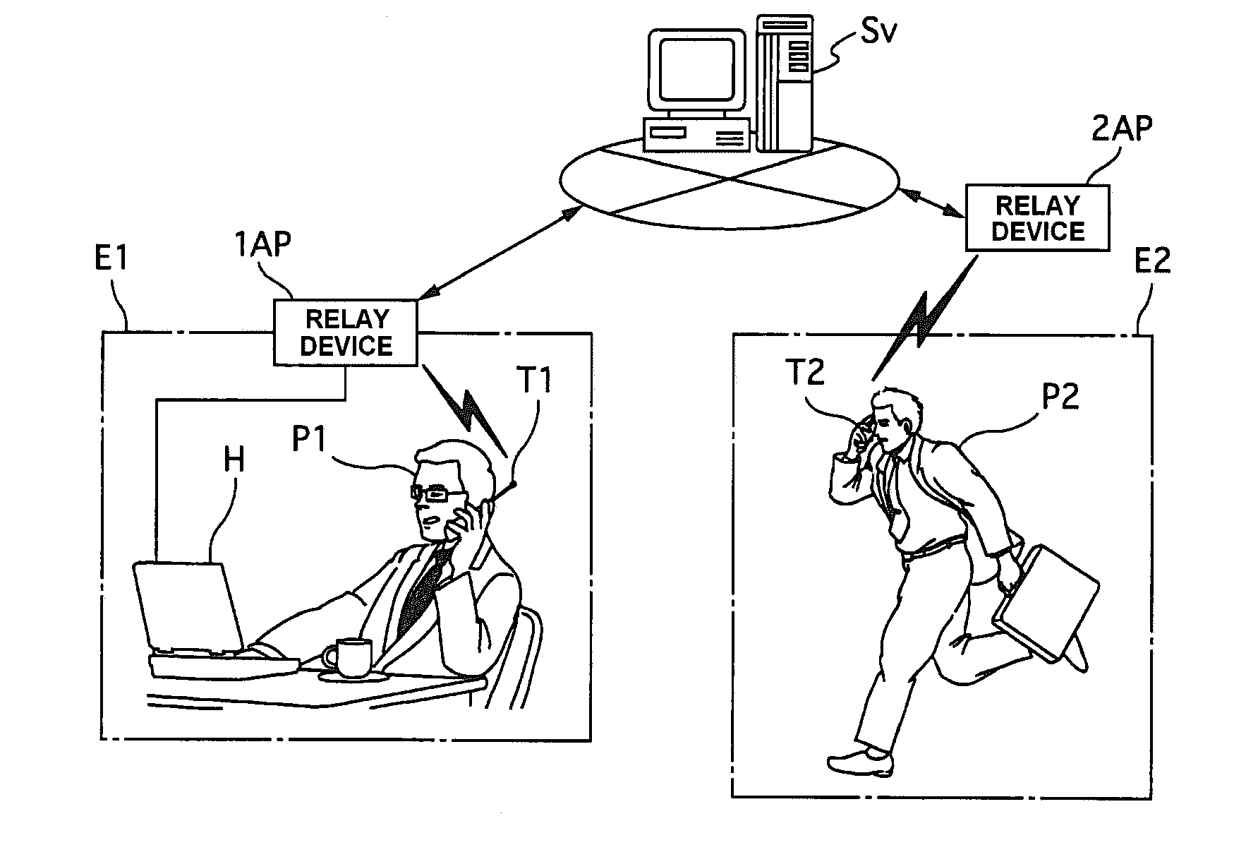
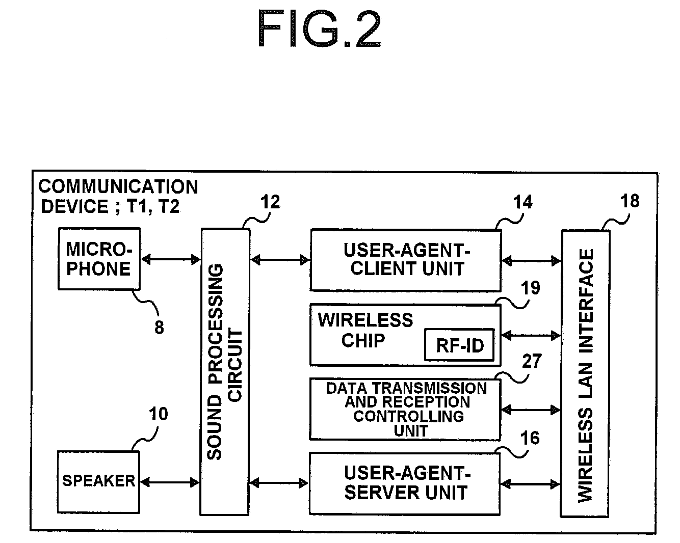
[0037]First, an IP telephone system according to a first embodiment will be described. The IP telephone system according to this embodiment is configured as a communication system to interconnect communication terminals to a server through an IP network. Herein, the communication terminals utilize communication technologies of the Internet. The server functions to allow communication (wireless communication) among the communication terminals in accordance with a predetermined communication protocol. It should be noted that the IP network is a generic name for the Internet or is a network having the same structure as that of the Internet, and the communication terminal can be connected to a wireless LAN (Local Area Network) or a wired LAN constructed in the IP network.

[0038]The server functions to follow a call setup of the communication terminals based on a communication system such as an SIP (Session Initiation Protocol) or a P2P (Peer to Peer). In this case, a communication device...

second embodiment

[0086]Next, the IP telephone system according to a second embodiment will be explained with reference to FIG. 5. It should be noted that the same structure is explained with reference to the drawing used in the above explanation, as required. In the IP telephone system according to the second embodiment, two communication data transmission modes (a transmission interrupting mode and a transmission resuming mode) are arbitrarily switched to transmit and receive the communication data (sound data shown as one example) between the communication devices T1, T2 and the server Sv during the communication between the communication devices T1, T2. That is, the IP telephone system according to this embodiment includes a data transmission and reception controlling unit. The data transmission and reception controlling unit mutually mode-switches between the transmission interrupting mode and the transmission resuming mode upon input of a predetermined command in a condition that communication ...

third embodiment

[0119]Next, the IP telephone system according to a third embodiment will be explained with reference to FIG. 6. It should be noted that the same structure is explained with reference to the drawing used in the above explanation, as required. In the IP telephone system according to the third embodiment, as shown in FIG. 6, two (telephone conversation) modes (a hold mode and a hold canceling mode) are arbitrarily switched to transmit and receive the communication data between the communication devices T1, T2 and the server Sv during the communication between the communication devices T1, T2. Here, the sound data is provided as one example of the communication data, the sound data being divided into the RTP packets and transmitted and received between the communication devices T1, T2 and the server Sv during the communication between the communication devices T1, T2 (FIG. 1A).

[0120]Therefore, the IP telephone system according to this embodiment includes a session controlling unit for m...


PUM


Abstract

An IP telephone system according to the present invention includes a plurality of communication devices T1, T2 allowed to mutually communicate through a network (IP network); a server for executing a connection starting process of communication between the communication devices, as well as for controlling communication data transmitted and received between the server and the communication devices during the communication between the communication devices; and a data transmission and reception controller for mutually switching, upon input of a predetermined command, a communication mode between a standard communication mode and a power-saving communication mode in a condition that communication connection is established between the communication devices upon execution of the connection starting process. The sound data is transmitted and received between the communication devices and the server in the standard communication mode. Transmission and reception between the communication devices and the server is stopped with respect to the sound data below a predetermined level while being continued with respect to the sound data beyond the predetermined level received in the power saving communication mode.

Description

CROSS-REFERENCE TO RELATED APPLICATIONS[0001]This application claims priorities of Japanese Patent Application Nos. 2007-215338, 2007-215339, and 2007-215340 filed on Aug. 21, 2007. The contents of these applications are incorporated herein by reference in their entirety.BACKGROUND OF THE INVENTION[0002]1. Field of the Invention[0003]The present invention relates to an IP telephone system which achieves low power consumption of communication devices in the field of communication technology with the use of an IP (Internet Protocol) network.[0004]1. Description of the Related Art[0005]Conventionally, there are known technologies of communicating various types of sound data such as music, for example, BGM, peoples' voice, and the like, through the IP (Internet Protocol) networks such as the Internet and intranets. Japanese Patent Application Laid-Open Publication No. 2005-45737 discloses an example of communication technology of this type. Such a sound communication technology has been...

Claims


Application Information

Patent Timeline
IPC IPC(8): H04L12/66
CPCH04L12/66
Inventor KOTERA, NORIOFUJIMOTO, JUNNONAKA, NOBUYUKI
Owner UNIVERSAL ENTERTAINMENT CORP
Learn More