Catheter for Enhanced Image Location Detection

a technology of enhanced image and location detection, applied in the field of catheters, can solve the problems of limited use of surface features and markings, 1i>b /i>of stubbs, etc., and achieve the effects of improving image location detection, highlighting different horizontal markings, and easy differentiation of markings

Inactive Publication Date: 2009-02-26
MEDICAL DIAGNOSTICS TECH
View PDF5 Cites 15 Cited by
  • Summary
  • Abstract
  • Description
  • Claims
  • Application Information

AI Technical Summary

Benefits of technology

[0006]According to the invention, a catheter with horizontal markings along a length of the catheter can be used to enhance image location detection and in performing 3D imaging processes which employ radiant wave energy such as ultrasound, MRI imaging, and CT scans. In an exemplary embodiment, the catheter will include a plurality of horizontal markings positioned along at least one length of said catheter between said distal end and said proximal end. Each horizontal marking includes two markings that are the same length, where a first of the two markings extends from said front side to the back side on a first side of the catheter, and where a second of the two markings extends from the front side to the back side on a second side of the catheter. The length of the markings will vary along the successive length of the catheter, but will always be is less than half the perimeter of said catheter. The two markings are positioned so that a front side gap and a back side gap of equal size are respectively positioned in horizontal alignment on the front side and the back side of said catheter. In one embodiment, the successive horizontal markings will have gap sizes which preferably gradually increase or gradually decrease in size along the length of the catheter so as to more easily differentiate one marking from another. Alternatively, the gap sizes for each marking can remain generally constant for successive markings or vary in a random or periodic fashion. The successive horizontal markings on the catheter can be spaced at relatively shorter or longer distances apart along the length of the catheter to further highlight different horizontal markings from one another. Alternatively or in addition, the successi

Problems solved by technology

While the markings on the catheters disclosed therein can allow for the identification of the location of an anatomical fea

Method used


Image

  • Catheter for Enhanced Image Location Detection
  • Catheter for Enhanced Image Location Detection
  • Catheter for Enhanced Image Location Detection

Examples


Embodiment Construction

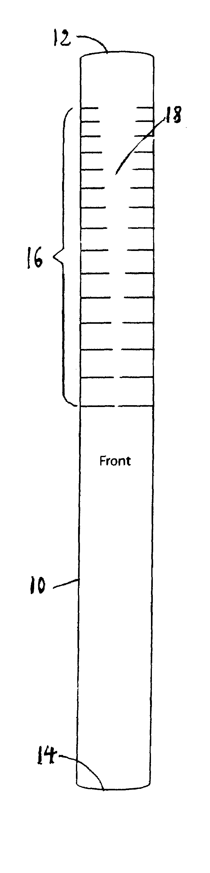
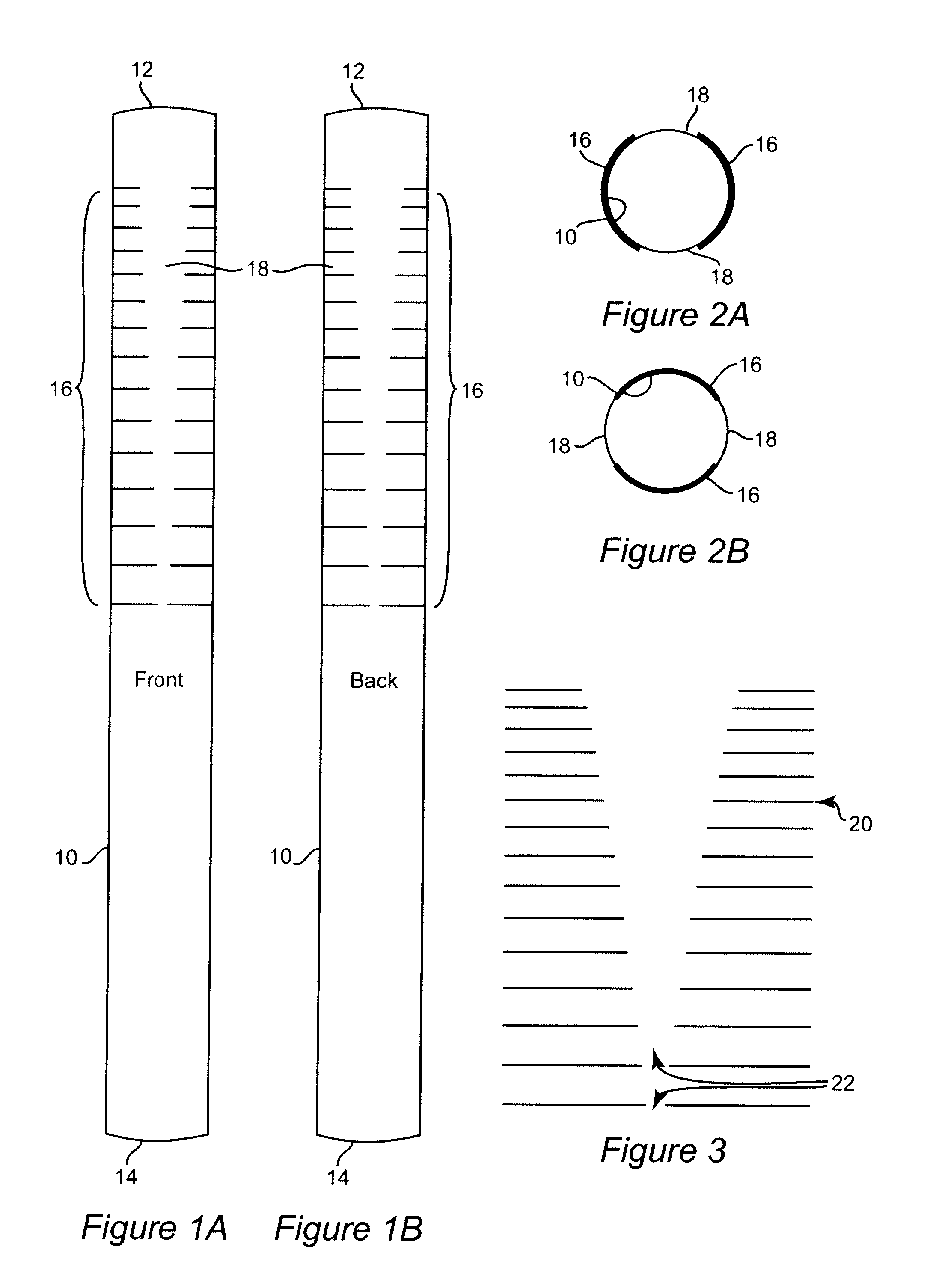
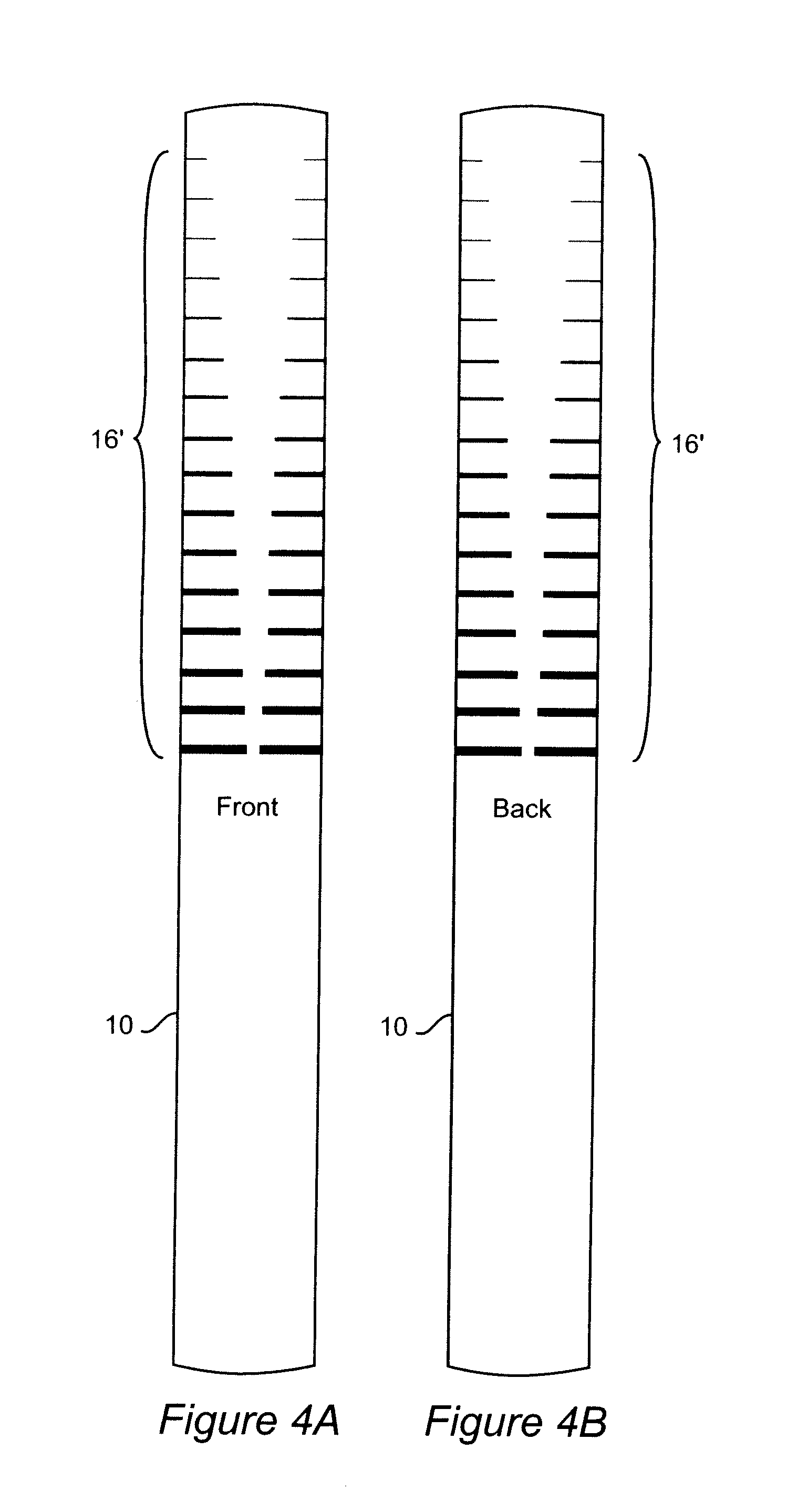
[0017]FIGS. 1a and 1b respectively show the front and back side of a catheter 10 having a proximal end 12 and distal end 14. Horizontal markings 16 are shown on the catheter 10 towards the proximal end 12. The horizontal markings 16 each have a gap 18 on the front surface (FIG. 1a) and back surface (FIG. 1b) which are in alignment with a diameter through the front and back surfaces. For exemplary purposes, the gap 18 is shown to be progressively larger towards the proximal end 12 of the catheter 10; however, it should be understood that the gap 18 could be progressively smaller towards the proximal end 12. Contrasting the catheter of FIG. 1a with the catheter of FIGS. 6a and 6b, in some applications the gap 18′ may be constant or may change in some other fashion than becoming progressively larger or smaller. With further reference to FIGS. 1a and 1b, in one embodiment the horizontal markings 16 are progressively closer together towards the proximal end in terms of the lengthwise or ...


PUM


Abstract

A catheter is used to assist in imaging, e.g., 3D imaging, an anatomical location in a human or veterinary subject. The catheter includes a plurality of horizontal markings which extend in the longitudinal direction between the distal and proximal ends. The horizontal markings can be made throughout the entire length of the catheter, or at one or more locations. At each location, the horizontal markings will appear as successive sets of markings. Each horizontal marking is made of two markings that are the same length. The two markings are arranged such that identically sized gaps between the ends of the markings are positioned on the front and back side of the catheter. In one embodiment, an image where the source and catheter are precisely aligned will show gaps of succeeding larger or smaller sizes. However, when the source is off center the gap lengths will be smaller or not exist. Particular marking locations can be highlighted by using relatively thinner or thicker markings and/or by spacing the markings progressively closer together or further apart.

Description

BACKGROUND OF THE INVENTION[0001]1. Field of the Invention[0002]The present invention generally relates to catheters used in medical operations for human and animal subjects, and also relates to medical imaging technologies.[0003]2. Background Description[0004]There are a wide variety of medical imaging techniques used in common practice today. Examples include, but are not limited to, computed tomography (“CT scan” or “CAT scan”) which employs the use x-ray beams rotated around a body party with three dimensional images of body parts including organs being developed from computer processing of several individual slices imaged through the body part; magnetic resonance imaging (MRI) which utilize high powered magnets to align hydrogen atoms in the body and computer processing of radio waves reflected from the hydrogen atoms where different tissues are identified by their reflection patterns (three dimensional imaging being similar to CT scans in that the three dimensional images are ...

Claims


Application Information

Patent Timeline
IPC IPC(8): A61M25/095
CPCA61B19/54A61M25/0108A61B2019/5425A61B90/39A61B2090/3925
Inventor BURKE, HARRY B.
Owner MEDICAL DIAGNOSTICS TECH
Why Eureka
Try Eureka