

Surgical operating apparatus
- Summary
- Abstract
- Description
- Claims
- Application Information
AI Technical Summary
Benefits of technology
Problems solved by technology
Method used
Image

Examples
first embodiment
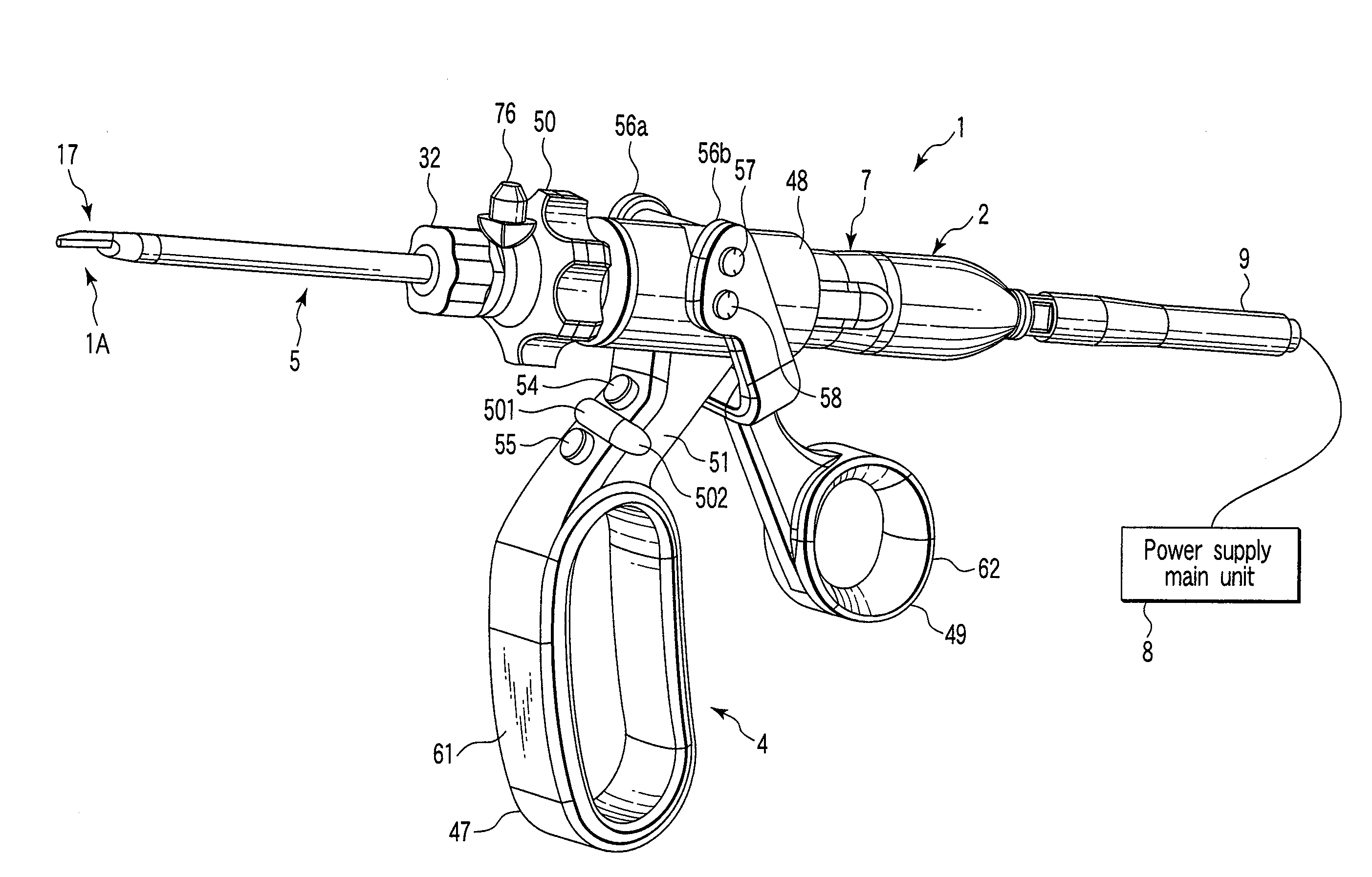
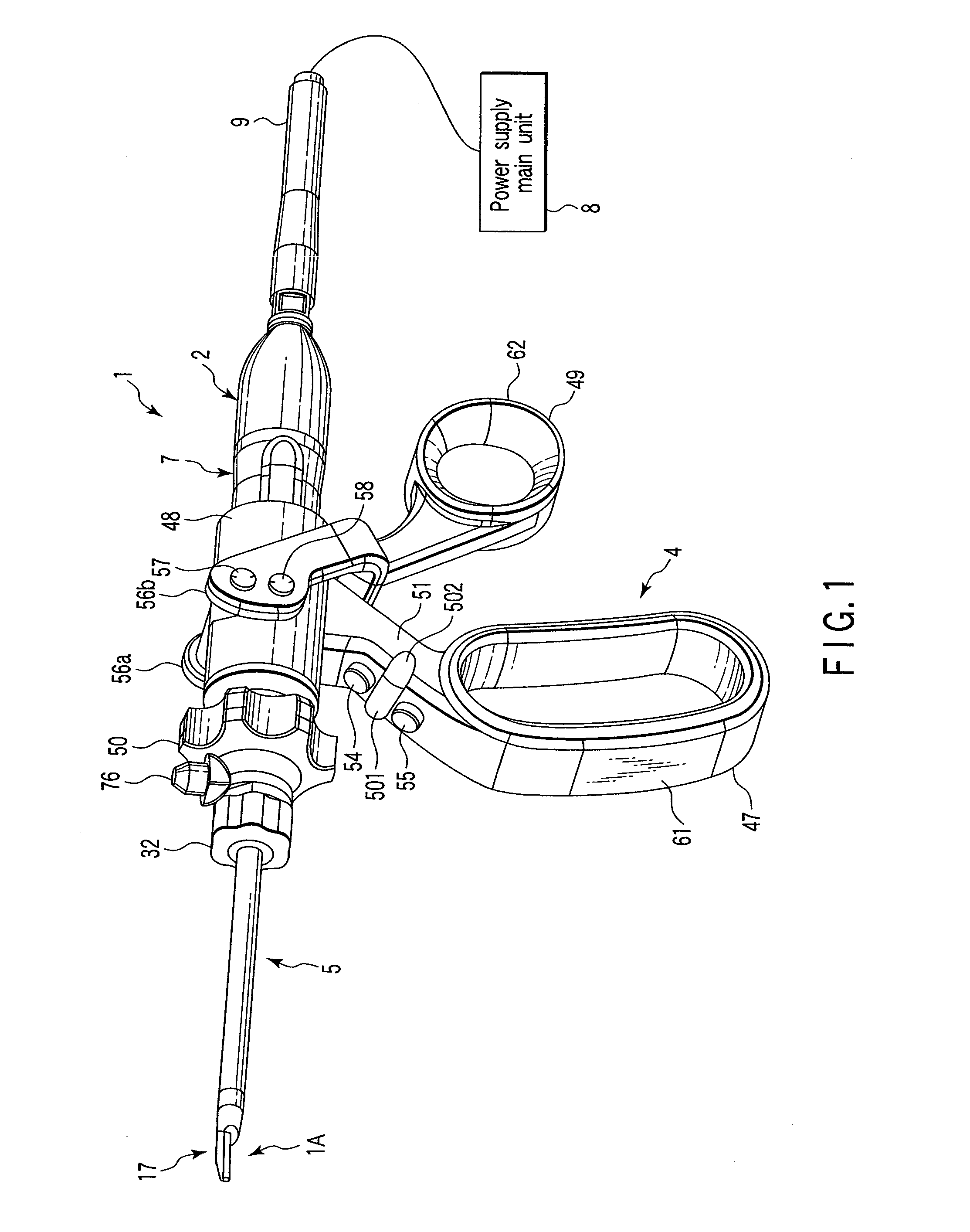
[0086]Hereinafter, the present invention will be described with reference to FIG. 1 to FIG. 52. FIG. 1 shows the schematic configuration of a whole hand piece 1 of an ultrasonic treatment apparatus which is a surgical apparatus in the present embodiment. The ultrasonic treatment apparatus in the present embodiment is an ultrasonic coagulation / incision treatment apparatus capable of administering a treatment such as incision, removal or coagulation of a living tissue by use of ultrasonic waves and also capable of administering a treatment with a high frequency.
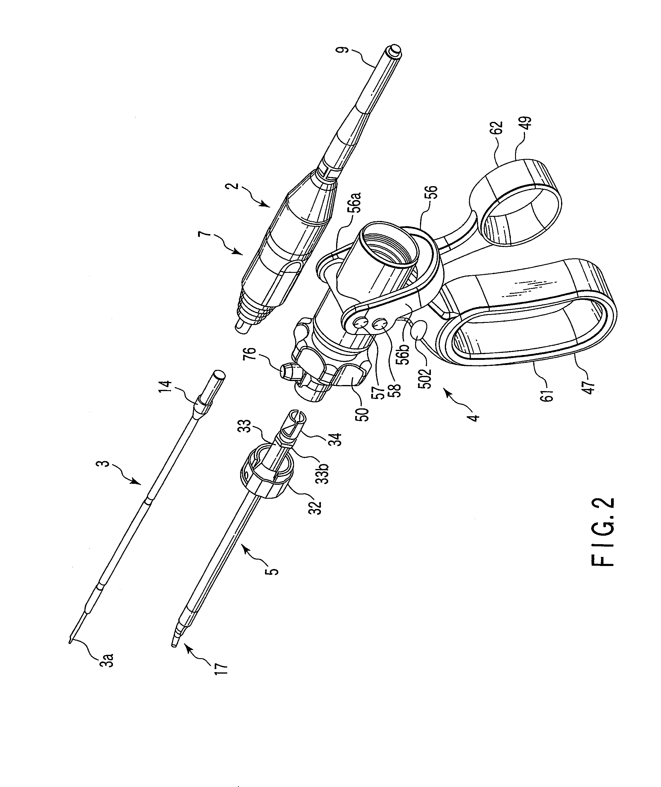
[0087]As shown in FIG. 2, the hand piece 1 has four units: a transducer unit 2, a probe unit (probe portion) 3, a handle unit (operation portion) 4, and a sheath unit (sheath portion) 5. These four units are removably coupled to each other.
[0088]In the transducer unit 2, there is incorporated a transducer 6 (see FIG. 41) described later for generating ultrasonic vibrations by a piezoelectric element which converts an electric c...
second embodiment
[0172]FIG. 53 shows the configuration of essential parts of a hand piece 1 of an ultrasonic treatment apparatus in the present invention. A movable handle 49 has a finger hook 601 upwardly protruding on the top of a thumb insertion ring portion 62.
[0173]In this configuration, during the use of this hand piece 1, the movable handle 49 can be operated so that the thumb H1 of the user is hooked on the finger hook 601 on the top of the thumb insertion ring portion 62. This makes it possible to adapt to the use of many users.
[0174]FIG. 54 shows an ultrasonic treatment apparatus in a third embodiment of the present invention. In the present embodiment, the configuration of the hand piece 1 of the ultrasonic treatment apparatus in the first embodiment (see FIGS. 1 to 52) is modified in the following manner.
[0175]That is, in a hand piece 1 in the present embodiment, a fixed handle (fixed handle element) 611 is fixed onto one side of a holding cylinder 48. Moreover, a movable handle (movable...
sixth embodiment
[0199]Moreover, the functions of the first switch 54, the second switch 55 and the third switch 511 are similar to those in the
PUM
 Abstract
Description
Claims
Application Information