Active surge control

Active Publication Date: 2009-02-26
CLEVELAND ELECTRIC LAB
View PDF6 Cites 49 Cited by
  • Summary
  • Abstract
  • Description
  • Claims
  • Application Information

AI Technical Summary

Benefits of technology

[0010]According to another embodiment, a device detects pre-surge temperature spikes with an array of temperature sensing elements. The array of temperature sensing elements may be fiber-optic sensing elements. The fiber-optic sensing elements may be EMI-immune

Problems solved by technology

However, too much compression at a given air flow causes instability and surging, a reversal in the direction of gas flow toward the inlet of the turbine engine, occurs.
Surging may result in hot g

Method used


Image

  • Active surge control
  • Active surge control
  • Active surge control

Examples


Embodiment Construction

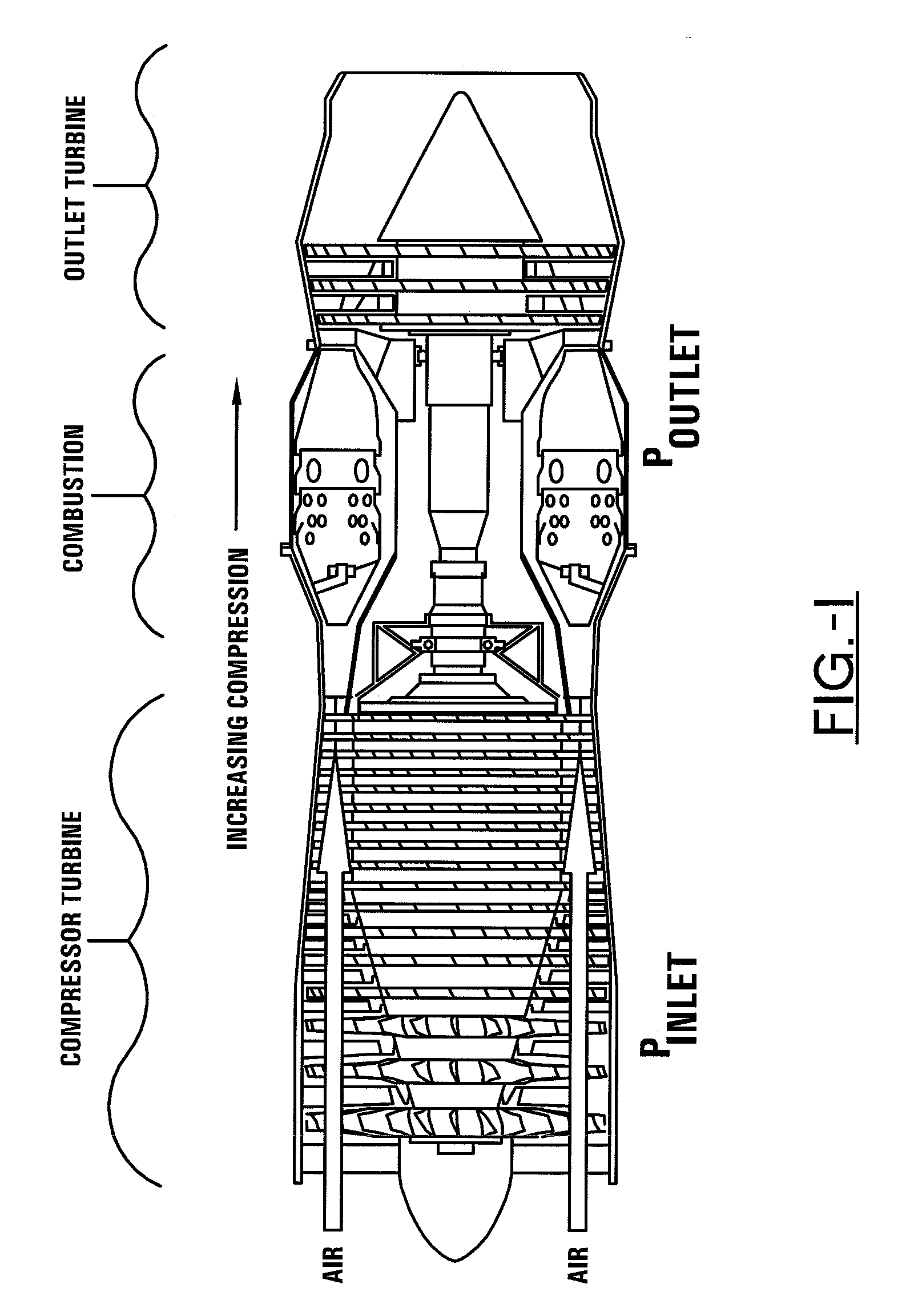
[0028]Referring now to the drawings wherein the showings are for purposes of illustrating the embodiments of the invention only and not for purposes of limiting the same, FIG. 1 shows a compressor in an axial-flow turbojet engine according to one embodiment. However, the principles and invention described in this document apply to all types of turbine engines including, without limitation, turbofan and turboprop engines and the like as well as any form of rotating compressor. For example, according to one embodiment, active surge control may be applied to a centrifugal compressor such as that which is used in the chemical industry. In another embodiment, intake throttling may be used to maximize centrifugal-compressor efficiency. Accordingly, active surge control may be used to move a compressor's butterfly valve or guide vanes.

[0029]According to one embodiment, the temperature sensing elements may be fiber Bragg gratings (FBGs). However, the scope of this invention is not limited t...


PUM


Abstract

The present invention generally relates to a system for preventing surges in turbine engines and/or rotating compressors. Furthermore, some embodiments comprise sensors for monitoring engine operating characteristics and detecting surge and pre-surge conditions. Some embodiments also include means for adjusting engine operation in response to sensor data. Still other embodiments relate to methods of preventing surges in turbine engines and/or rotating compressors.

Description

I. CROSS REFERENCE TO RELATED APPLICATIONS[0001]This application claims priority to Provisional Application Ser. No. 60 / 957,287 filed Aug. 22, 2007 now pending, which is incorporated herein by reference in its entirety. This application also claims priority to Provisional Application Ser. No. 60 / 983,330 filed Oct. 29, 2007 now pending, which is incorporated herein by reference in its entirety.II. BACKGROUND OF THE INVENTION[0002]A. Field of Invention[0003]This invention pertains to the art of methods and apparatuses regarding the manufacture and control of turbine engines, and more particularly to methods and apparatuses regarding the active surge control of turbine engines.[0004]B. Description of the Related Art[0005]Turbine engines of all types compress the combustion air in the first part of the working cycle. High compression of the inlet air results in optimal engine efficiency. However, too much compression at a given air flow causes instability and surging, a reversal in the ...

Claims


Application Information

Patent Timeline
IPC IPC(8): F04D27/02F02C9/18
CPCF02C9/28F04D27/001F05D2270/091F04D27/0284F05D2270/021F04D27/0261Y02B30/70
Inventor WAY, DONALD R.LANTZ, JOEL
Owner CLEVELAND ELECTRIC LAB
Why Eureka
Try Eureka