Check patentability & draft patents in minutes with Patsnap Eureka AI!

Mode-switching system and camera

Inactive Publication Date: 2009-02-26
PENTAX RICOH IMAGING CO LTD
View PDF7 Cites 7 Cited by
  • Summary
  • Abstract
  • Description
  • Claims
  • Application Information

AI Technical Summary

Benefits of technology

[0008]According to the present invention, a mode-switching system, comprising plural switches, a timer, a reset block, and a controller, is provided. The mode-switching system switches an operation mode of a first unit to one of normal and power-saving modes. The first unit is driven with normal power in the normal mode and with less power in the power-saving mode. The plural switches separately correspond to specific functions. The specific functions are provided to the first unit. Each of the specific functions is carried out when the corresponding switch is switched o

Problems solved by technology

However, an operation mode is not always adequately switched to the power-saving mode because the strap is not always drawn when the camera is idle.

Method used


Image

  • Mode-switching system and camera
  • Mode-switching system and camera
  • Mode-switching system and camera

Examples


first embodiment

[0017]In FIG. 1, a digital camera 10 of the first embodiment comprises a photographic optical system 11, an imaging device 12, an analog front end (AFE) 13, a digital signal processor (DSP) 14, a system controller 15 (controller, reset block, setting block, renewal block), an input block 16, a liquid crystal display (LCD) 17, a timer 18, and other components.

[0018]The photographic optical system 11 is optically connected to the imaging device 12. An optical image of an object through the photographic optical system 11 is incident on the light-receiving surface of the imaging device 12. The imaging device 12 is, for example, a CCD area sensor. When the imaging device 12 captures the optical image of the object upon its light-receiving surface, the imaging device 12 generates an image signal corresponding to the captured optical image.

[0019]The photographic optical system 11 comprises plural lenses, including a focusing lens (not depicted) and a zoom lens (not depicted). The focusing ...

second embodiment

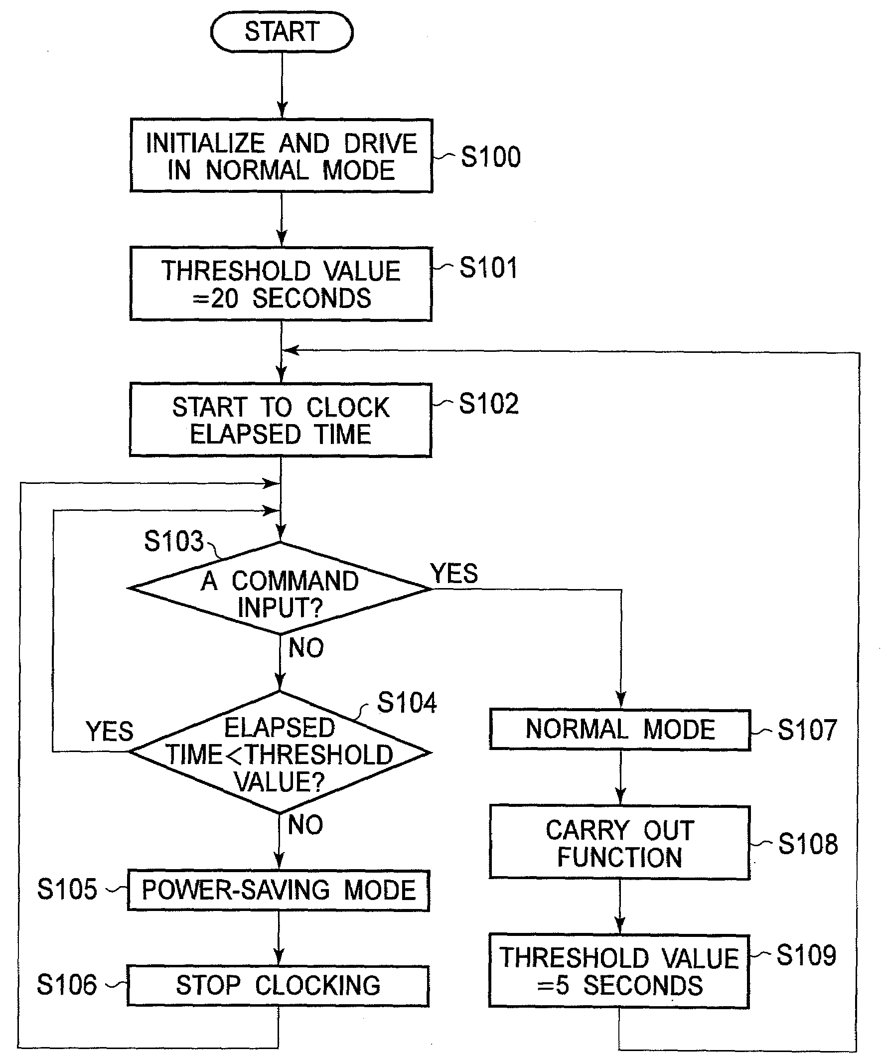
[0066]The average of the previous threshold value for switching and the elapsed time clocked by the timer 18, is set as the renewed threshold value for switching in the However, a renewed threshold value for switching can be calculated according to any renewal methods using the elapsed time. For example, a minimum time margin may be added to the elapsed time, and the average of the previous threshold value for switching and the added elapsed time can be calculated as the renewed threshold value for switching in order to prevent the renewed threshold value for switching from being too short.

[0067]The threshold value for switching is renewed whenever a single command is input to the input block 16 in the second embodiment. However, the threshold value for switching is renewed so that the threshold value for switching may change when commands are input in rapid succession as opposed to singly. For example, the threshold value for switching renewed when a release button is fully depres...


PUM


Abstract

A mode-switching system, comprising plural switches, a timer, and a controller, is provided. The mode-switching system switches an operation mode of a first unit to one of normal and power-saving modes. The plural switches separately correspond to plural specific functions. Each of the specific functions is carried out when the corresponding switch is switched on. The timer clocks the elapsed time since the switching operation is carried out for any of the switches. The controller switches the operation mode to the power-saving mode from the normal mode when the elapsed time exceeds a threshold value determined for the switch for which the latest switching operation has been carried out. The threshold value is determined individually for each of the switches.

Description

BACKGROUND OF THE INVENTION[0001]1. Field of the Invention[0002]The present invention relates to a mode-switching system that switches an operation mode of a unit, such as a camera, to one of a normal and power-saving modes.[0003]2. Description of the Related Art[0004]Various electric apparatuses which can carry out power-related functions are known. In particular, a portable apparatus such as a camera, to which a battery supplies power, is provided with a power-saving mode in order to prolong its period of use. Power for driving various components of the portable apparatus is cut back from normal usage in the power-saving mode. There is known an auto switching system, which switches an operation mode to the power-saving mode if no commands are input for a specific period.[0005]Even when a portable apparatus is idle, the auto switching system does not switch an operation mode to the power-saving mode unless no command has been input for a specific period. Japanese Unexamined Patent ...

Claims


Application Information

Patent Timeline
IPC IPC(8): G06F1/00
CPCH04N5/232H04N5/23245H04N5/23241H04N23/651H04N23/667
Inventor YAMAMOTO, YASUHIRO
Owner PENTAX RICOH IMAGING CO LTD
Features
  • R&D
  • Intellectual Property
  • Life Sciences
  • Materials
  • Tech Scout
  • Unparalleled Data Quality
  • Higher Quality Content
  • 60% Fewer Hallucinations
Learn More