Web Measurement Device

a measurement device and web technology, applied in the field of web measurement systems, can solve problems such as frequent maintenance, contacting devices, and holes or even sheets breaking on thin paper grades

Active Publication Date: 2009-03-05
ABB LTD
View PDF17 Cites 36 Cited by
  • Summary
  • Abstract
  • Description
  • Claims
  • Application Information

AI Technical Summary

Benefits of technology

[0009]A second optical sensor probe is positioned in the second sensor head, and is adapted to measure the distance to the second side of the moving web. At least one guide bar is secured to the first sensor head directing air toward the web. A peripheral slot is on the second sensor head through which air is directed toward the web. The peripheral slot is located inwardly of the at least one guide bar.

Problems solved by technology

In particular, sensors that contact the sheet simultaneously from both sides have a risk of pinching sheets containing lumps or defects, resulting in the sensors causing holes or even sheet break on thin paper grades.
Further, non-contacting sensors eliminate issues related to dirt buildup and wear that may cause measurement inaccuracies, thereby leading to frequent maintenance.
One particular drawback to prior art non-contacting devices are the issues related to light penetration.
Most paper has some degree of translucency, making the exterior surface position difficult to establish by traditional optical means.
This often leads to optically measured thickness values that are too low.
These errors can be significant, and depending upon the paper grades, laser measurement can generate optical thickness measurements that are only 50% of the true value.
Thus, none of the current non-contacting sensor solutions offer acceptable accuracy for the majority of paper grades, and furthermore, they tend to be complex in design and unreliable.

Method used


Image

  • Web Measurement Device
  • Web Measurement Device
  • Web Measurement Device

Examples


Embodiment Construction

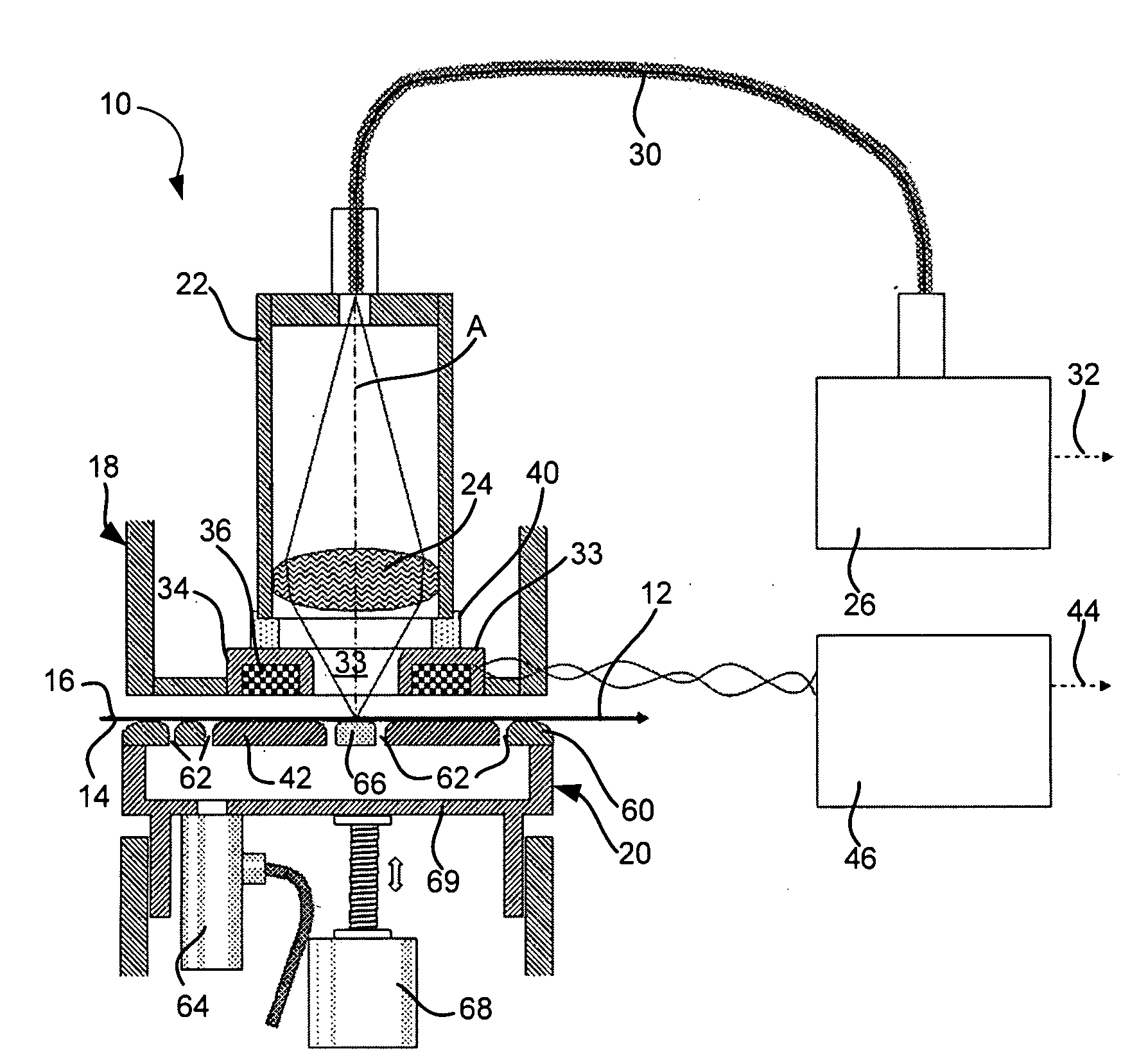
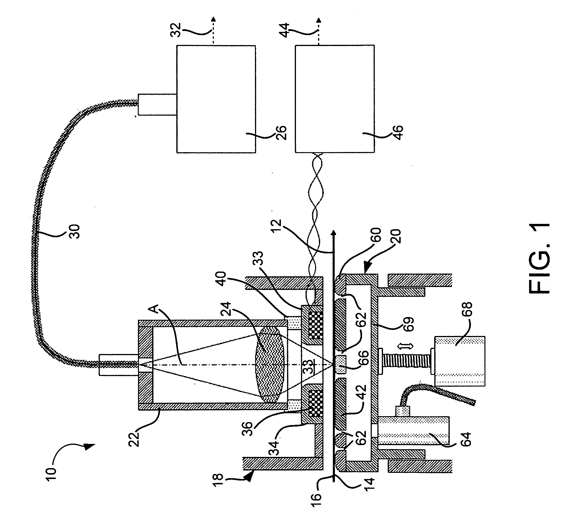
[0034]Referring now to FIG. 1, a gauge measurement device (hereinafter device 10) is shown and generally indicated by the numeral 10. Device 10 may be installed and used in a web making process line, for example, a paper making line. When installed, device 10 is positioned in close proximity to a moving web 12 for measurement thereof. Though the present invention is particularly useful for paper making applications, device 10 may be used to measure any type of continuously produced web. Further, one or more devices 10 may be positioned at any point along the continuous web production process to continuously measure web thickness at multiple points in the process.

[0035]The web 12 may move at high speeds through device 10 in the machine direction D. In the example where web 12 is a paper product, production line speeds in paper manufacturing can reach 100 km per hour or more. Device 10 contacts a bottom surface 14 of web 12, while a top surface 16 is not contacted and is measured opti...


PUM


Abstract

A sensor is provided that measures web caliper using optical and magnetic measuring devices. The optical measuring devices may employ a confocal chromatic aberration method to accurately determine the distance to the moving web and the magnetic devices may be ferrite core coil and target. Means of stabilizing a moving web are included for improving dynamic measurement accuracy.

Description

CROSS REFERENCE TO RELATED APPLICATION[0001]This application claims the priority of U.S. provisional patent application Ser. No. 60 / 969,373 filed on Aug. 31, 2007 entitled “Web Thickness Measurement Device,” the contents of which are relied upon and incorporated herein by reference in their entirety, and the benefit of priority under 35 U.S.C. 119(e) is hereby claimedFIELD OF THE INVENTION[0002]This invention relates to web measurement systems.DESCRIPTION OF THE PRIOR ART[0003]Sheet materials, such as paper, are produced in thin continuous webs and require highly accurate thickness (caliper) measurement and control. Commonly, these measurements are accomplished by means of sensors that physically contact the web at both the top and bottom side. Also, various non-contacting sensors have been developed that may be fully non-contacting (no physical contact), or sensors that contact physically contact sheet at only one side.[0004]The speed of papermaking machinery has increased dramatic...

Claims


Application Information

Patent Timeline
Patent Type & Authority Applications(United States)
IPC IPC(8): G01B3/00G01B11/14G01B9/02
CPCG01B7/023G01B7/107G01N33/346G01B11/0691G01B11/026G01B2210/44G01B2210/50G01N21/86
Inventor HELLSTROM, AKENAIMI, RAMBODO'HORA, MICHAEL
Owner ABB LTD
Why Eureka
Try Eureka