Liquid tank

a technology of liquid tank and discharge port, which is applied in the direction of liquid degasification, separation processes, mechanical apparatus, etc., can solve the problems that the hydrocarbon fluid containing the bubbles discharged from the bubble exhaust port may unfavorably be fed out from the delivery port, and achieve the effect of reducing the installation area of the fluid tank and ensuring the removal of the bubbles

Inactive Publication Date: 2009-03-05
KOMATSU LTD
View PDF3 Cites 8 Cited by
  • Summary
  • Abstract
  • Description
  • Claims
  • Application Information

AI Technical Summary

Benefits of technology

[0033]With this arrangement, the elements in the tank are substantially linearly disposed. Accordingly, the tank main body is formed thin. As a result, an installation area of the fluid tank can be reduced.
[0034]In addition, the elements that may take in air when the fluid surface is lowered, such as the bubble removing device or the like, are disposed closer to the center of the tank where the influence of lowering of the fluid surface is minor. Accordingly, air is prevented from being taken in. As a result, bubbles can be more securely removed.

Problems solved by technology

In addition, the hydraulic circuit is sometimes provided with a bubble removing device for removing bubbles in the hydraulic fluid because bubbles generated in the hydraulic circuit may damage the pump.
With this arrangement, since the bubble exhaust port of the bubble removing device and the delivery port of the hydraulic tank are closely disposed on account of the size reduction of the hydraulic tank, the hydraulic fluid containing the bubbles discharged from the bubble exhaust port may unfavorably be fed out from the delivery port together with the hydraulic fluid from which the bubbles have been removed.

Method used


Image

  • Liquid tank
  • Liquid tank
  • Liquid tank

Examples


first embodiment

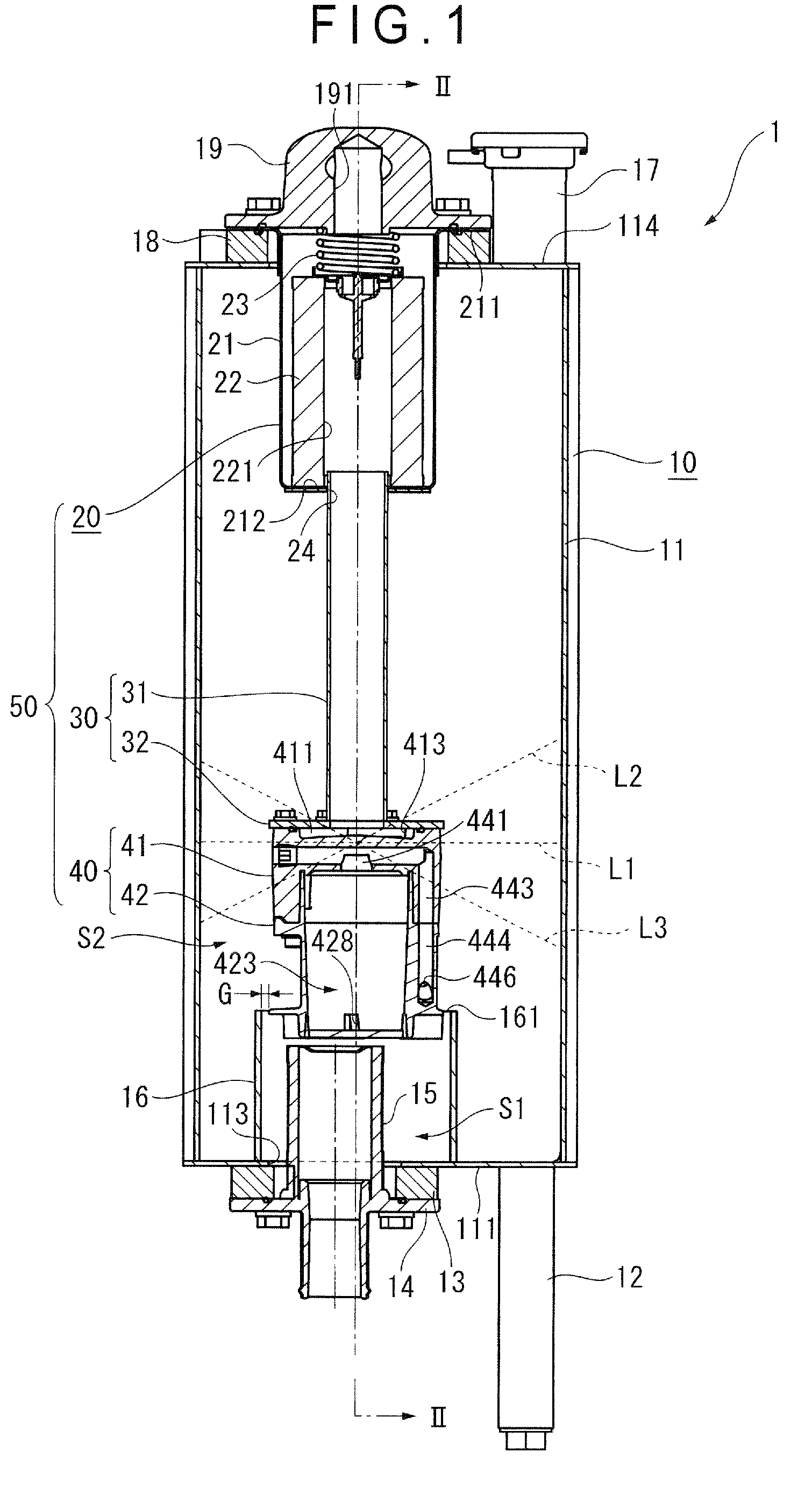
[0057]A first embodiment of the present invention will be described below with reference to FIGS. 1 to 8.

[0058]A hydraulic tank (fluid tank) 1 is equipped on a construction machine, for example, and is used to contain a hydraulic fluid (a fluid) for operating work equipment. For this purpose, the hydraulic tank 1 is connected via a hydraulic line with a pump (not shown), a control valve, a cylinder that forms the work equipment, an oil cooler and the like, which form a hydraulic circuit and a hydraulic system.

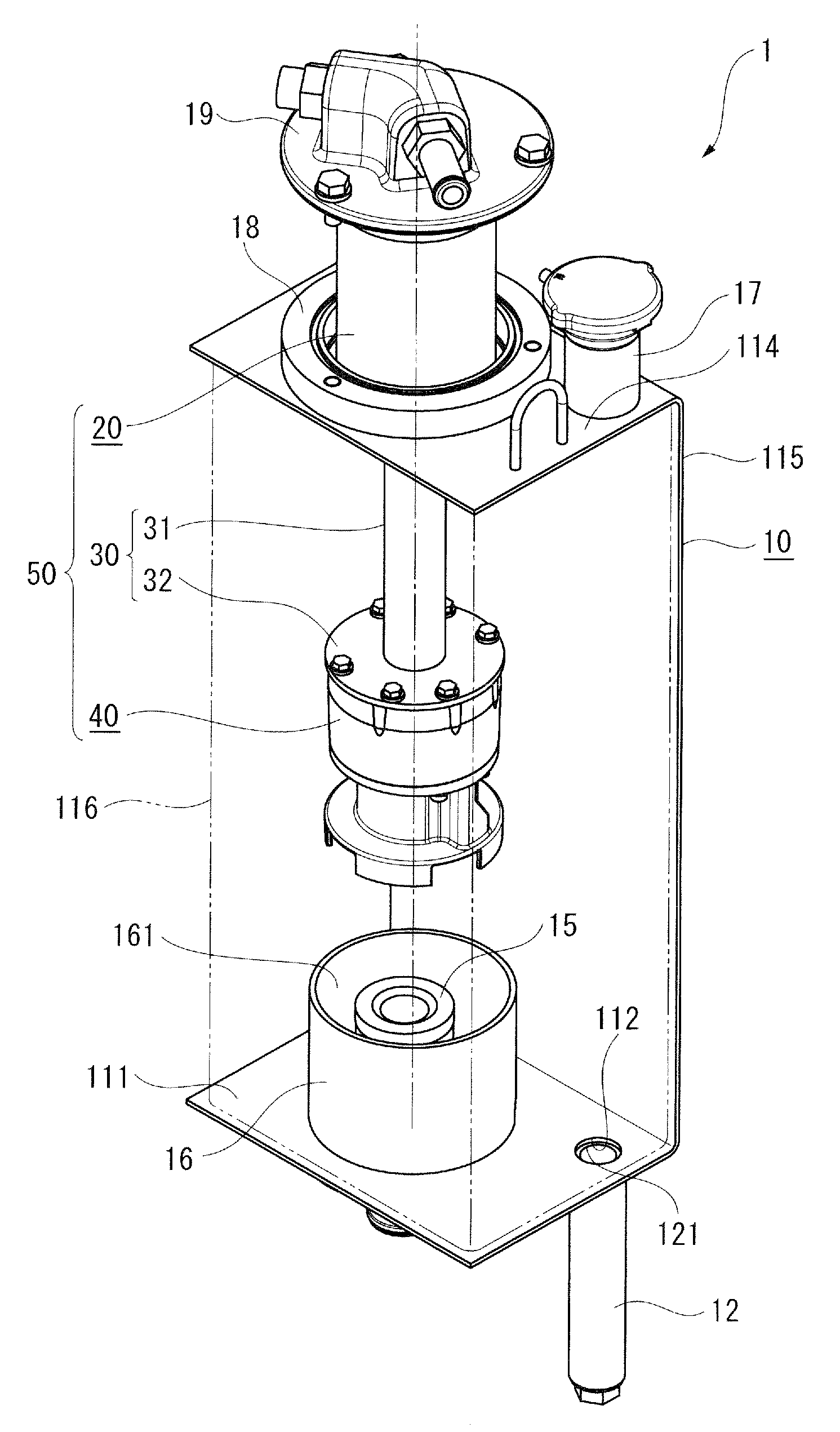
[0059]As shown in FIGS. 1 to 4, the hydraulic tank 1 includes a tank main body 10, a filter 20, a connecting portion 30 and a bubble removing device 40. The filter 20, the connecting portion 30 and the bubble removing device 40 are contained in the tank main body 10 in a so-called “hanging in midair” manner.

[0060]Specifically, the tank main body 10 includes a box-shaped body 11, which includes a bottom plate 111 on which a drain port 112 for draining a hydraulic fluid in the hy...

second embodiment

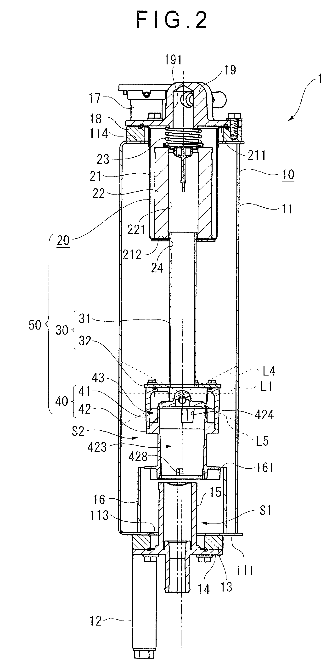
[0089]A second embodiment of the invention will be described with reference to FIGS. 9 and 10. Note that the members and the like that are the same as ones described above will be provided with the same numerals and description thereof will be omitted in the following embodiments starting from the second embodiment.

[0090]In the first embodiment, the bubble removing device 40, the delivery port 113 and the strainer 15 are substantially linearly disposed with the central axes being slightly misaligned from one another.

[0091]On the contrary, the second embodiment differs from the first embodiment in that the bubble removing device 40, the delivery port 113 and the strainer 15 are linearly disposed sharing the central axis.

[0092]Accordingly, a width of the tank main body 10 in an installed hydraulic tank 1 can be reduced to diminish an installation area of the hydraulic tank 1 from that in the first embodiment. In addition, elements that may take in air can be disposed even closer to th...

third embodiment

[0093]A third embodiment of the invention will be described below with reference to FIGS. 11 and 12.

[0094]In the first and second embodiments, the bubble removing device 40, the delivery port 113 and the strainer 15 are linearly or substantially linearly disposed with the guide 16 for covering them being formed in a cylindrical shape.

[0095]On the contrary, in the third embodiment, the bubble removing device 40 and the strainer 15 are juxtaposed in a widthwise direction of the hydraulic tank 1. In other words, the bubble removing device 40, the delivery port 113 and the strainer 15 are not substantially linearly disposed. Correspondingly, the guide 16 is provided in a deformed shape.

[0096]Specifically, as shown in FIGS. 11 and 12, the bubble removing device 40 is juxtaposed with the strainer 15 in a manner that a lower end of the bubble removing device 40 is lower than an upper end of the strainer 15.

[0097]A portion of the guide 16 where the strainer 15 is contained is shaped in a he...


PUM

PropertyMeasurementUnit
widthaaaaaaaaaa
sizeaaaaaaaaaa
convex shapeaaaaaaaaaa

Abstract

A fluid tank includes a tank main body that contains a fluid and a bubble removing device that is provided to an inside of the tank main body and removes bubbles contained in the fluid. The tank main body includes a partition that partitions the inside of the tank main body to at least two sides and a delivery port through which the fluid is fed to an outside. The bubble removing device has an outflow port through which the fluid from which the bubbles have been removed flows to the inside of the tank main body and a bubble exhaust port through which the bubbles which have been removed are discharged to the inside of the tank main body. The delivery port is provided adjacent to the outflow port relative to the partition. The partition partitions the inside of the tank main body to a side in which the outflow port and the delivery port are provided and a side of the bubble exhaust port.

Description

TECHNICAL FIELD[0001]The present invention relates to a fluid tank, and in particular, to a fluid tank having a bubble removing device that removes bubbles (air) in a fluid.BACKGROUND ART[0002]In a conventional constriction machine, a portion of work equipment such as a cylinder is typically driven by a hydraulic fluid. Consequently, the construction machine is provided with a hydraulic circuit for driving the cylinder or the like. The hydraulic circuit is provided with, for example, a hydraulic tank and a pump for pumping the hydraulic fluid from the hydraulic tank. In addition, the hydraulic circuit is sometimes provided with a bubble removing device for removing bubbles in the hydraulic fluid because bubbles generated in the hydraulic circuit may damage the pump. Since demands for size reduction of components equipped on construction machines have been on the rise, a lot of construction machines are provided with a bubble removing device in a hydraulic tank in recent years.[0003]...

Claims


Application Information

Patent Timeline
Patent Type & Authority Applications(United States)
IPC IPC(8): B01D19/00F15B21/044
CPCB01D19/0031B01D19/0042F15B21/044F15B1/26E02F9/22
Inventor KONISHI, AKIKONOHARA, TATSUROYOKOO, KATSUMIISHII, SHOTAROKANAYAMA, NOBORU
Owner KOMATSU LTD
Why Eureka
Try Eureka