Liquid application apparatus and method, and image forming apparatus
Inactive Publication Date: 2009-03-05
FUJIFILM CORP
View PDF3 Cites 15 Cited by
Summary
Abstract
Description
Claims
Application Information
AI Technical Summary
This helps you quickly interpret patents by identifying the three key elements:
Problems solved by technology
Method used
Benefits of technology
Benefits of technology
[0013]The present invention has been contrived in view of these circumstances, an object thereof being to provide a liquid application apparatus and an image forming apparatus using same, whereby the control of the application range can be improved in an application method using a roller member, while also minimizing damage caused to the members by components in the application liquid, in addition to drying and solidification of the liquid.
Problems solved by technology
In the invention described in Japanese Patent Application Publication No. 4-64488, although it is possible to stabilize application by removing remaining liquid by means of air or liquid, it is not suitable for high-speed processing since the doctor blade needs to be separated from the gravure roller frequently.
Furthermore, it is also difficult to control application in the conveyance direction and the breadthways direction.
In the invention disclosed in Japanese Patent Application Publication No. 10-230201, although it is possible to reduce affixation onto the roller surface, there is a problem in that application non-uniformities are liable to occur due to the effects of residual fixed material.
Furthermore, when the application liquid in the application liquid tank is separated, then it is possible to control application in the conveyance direction, but liquid trails are liable to occur and the response is not satisfactory.
Moreover, non-uniformities are liable to occur in the breadthways direction due to air blowing, and it is difficult to control the application thickness by means of air blowing.
In the invention disclosed in Japanese Patent Application Publication No. 2006-95489, the treatment liquid which has dried and solidified is liable to become attached to the roller, and even when application has been halted, liquid trails are liable to occur and therefore the control characteristics cannot be regarded as satisfactory.
When an image is formed on a cut paper by means of this method, then although good reverse rotation application is achieved on the gravure roller, which enables good film thickness uniformity when applying the undercoating liquid (see Japanese Patent Application Publication No. 2006-95489), it is difficult to control the application range and there are cases where the undercoating liquid adhering to portions outside the paper becomes attached to the transfer roller, and the intermediate transfer body becomes soiled by retransfer of this liquid.
Furthermore, in cases where the undercoating liquid is acidic, then corrosion of the structural members, such as the transfer roller, may be caused by the liquid.
Moreover, in cases where liquid has been attached to the gravure roller for a long period of time also, there is a possibility of drying solidification or damage resulting from corrosion.
Method used
Image
Click on the blue label to locate the original text in one second.
Reading with bidirectional positioning of images and text.
Examples
first embodiment
General Composition of Inkjet Recording Apparatus
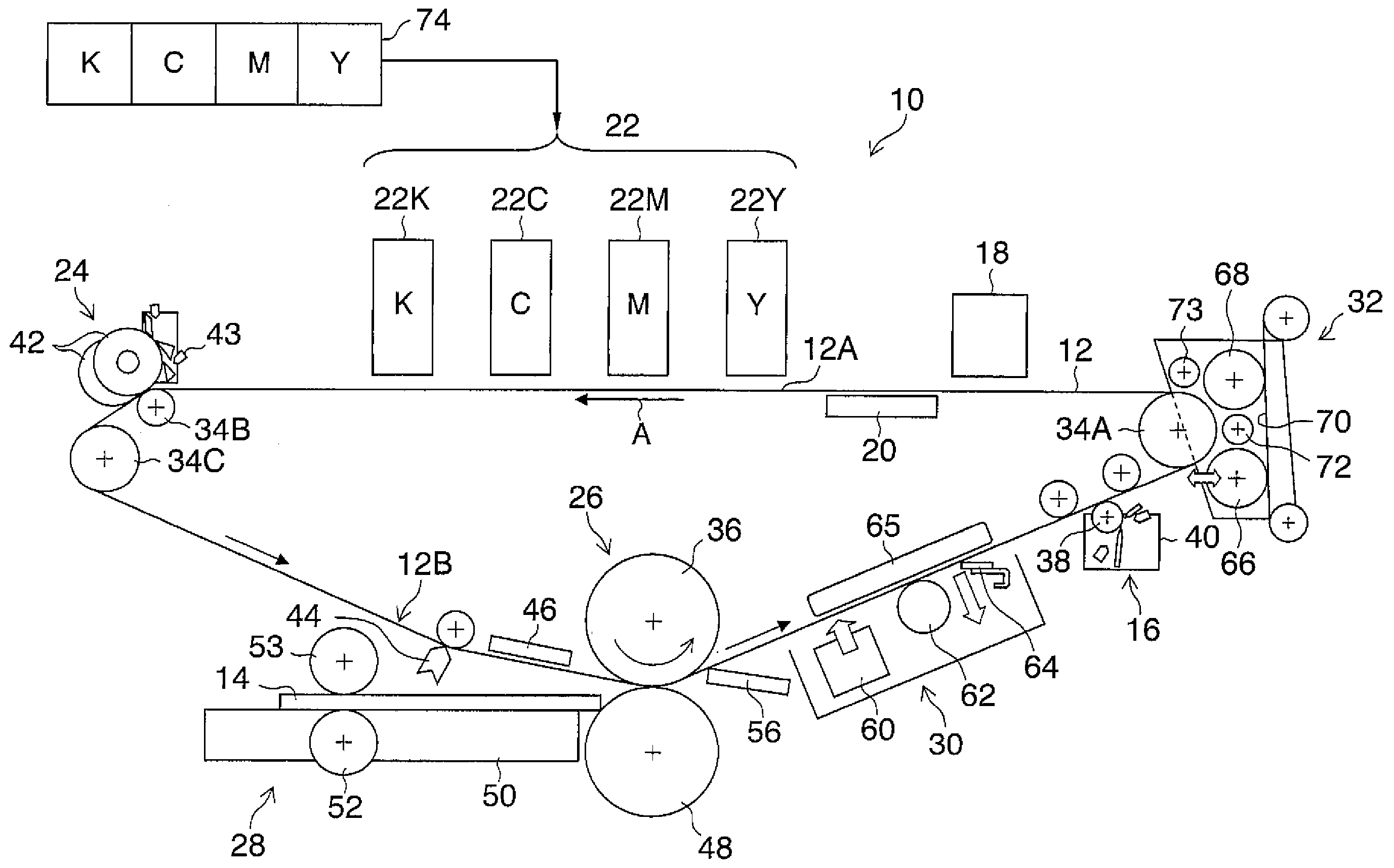
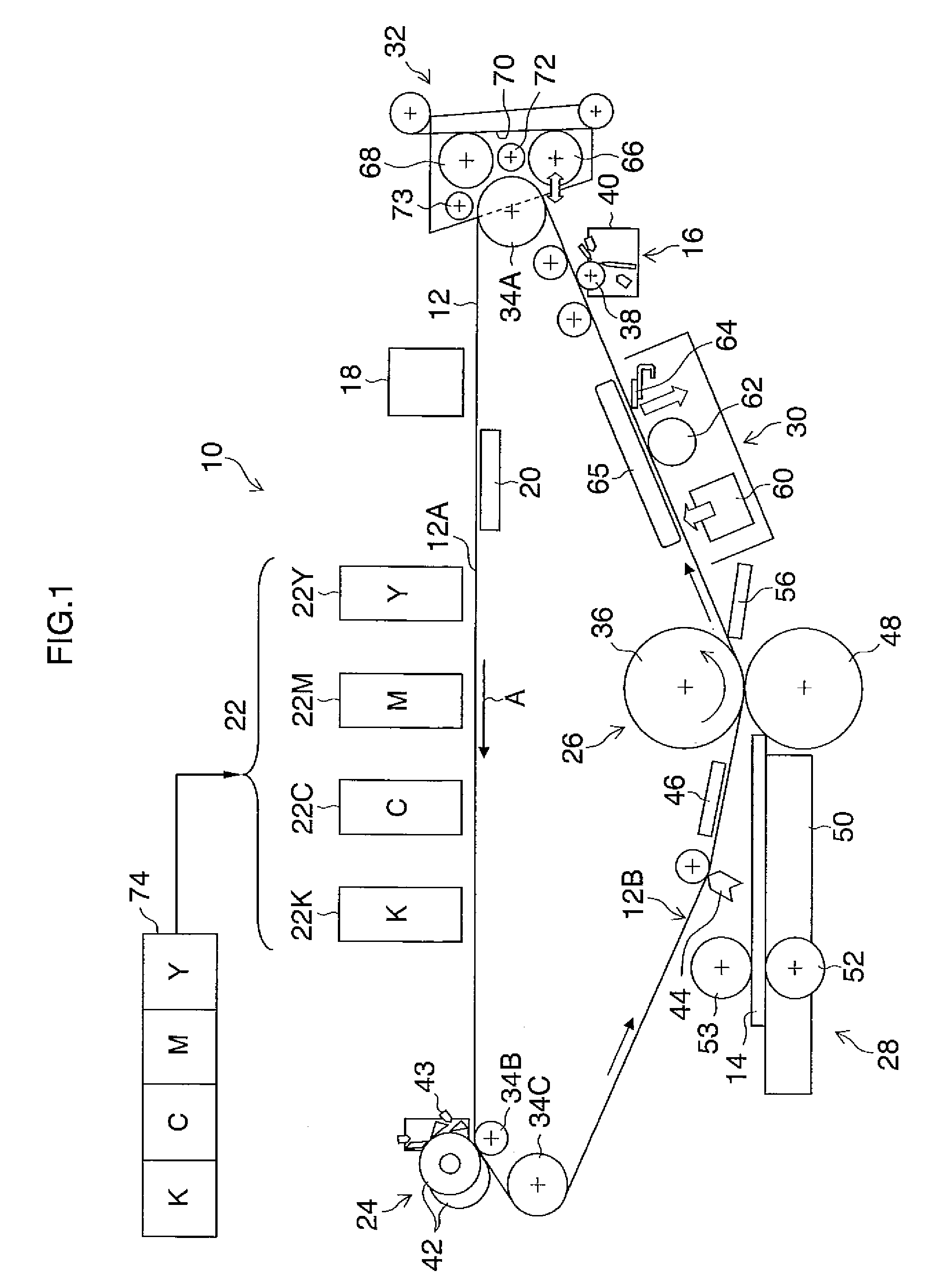
[0062]Firstly, an inkjet recording apparatus which forms an image forming apparatus according to an embodiment of the present invention will be described. FIG. 1 is a diagram of the general composition of an inkjet recording apparatus according to a first embodiment. As shown in FIG. 1, the inkjet recording apparatus 10 according to the present embodiment is a recording apparatus using a transfer method which records an image (primary image) on an intermediate transfer body 12, which is a non-permeable body, and then forms a main image (secondary image) by transferring this image to a recording medium 14, such as a normal paper The principle compositional elements of this inkjet recording apparatus 10 are: a treatment liquid application unit 16 (corresponding to the “liquid application apparatus” according to the present invention) which applies an aggregation treatment agent (hereinafter referred to simply as “treatment liquid” in th...
example 1
TREATMENT LIQUID EXAMPLE 1
[0126]A treatment liquid (Example 1) is prepared according to the composition shown in Table 1. Thereupon, the physical properties of the treatment liquid (Example 1) thus obtained were measured, and the pH was 3.6, the surface tension was 28.0 mN / m, and the viscosity was 3.1 mPa·s.
TABLE 1MaterialWeight %2-pyrrolidone-5-carboxylic acid (made by10Tokyo Chemical Industry Co., Ltd.)Lithiumhydroxide-hydride (made by Wako2Pure Chemical Industries, Ltd.)Olfine E1010 (made by Nissin Chemical1Industry Co., Ltd.)Deionized water87
example 2
TREATMENT LIQUID EXAMPLE 2
[0127]Moreover, a treatment liquid (Example 2) containing a surfactant is prepared according to the composition shown in Table 2. Thereupon, the physical properties of the treatment liquid (Example 2) thus obtained were measured, and the pH was 3.5, the surface tension was 18.0 mN / m, and the viscosity was 10.1 mPa·s.
[0129]An example of the preparation of an ink used in the present embodiment is described below.
[0130]A solution comprising 6 parts by weight of styrene, 11 parts by weight of stearyl methacrylate, 4 parts by weight of styrene macromer AS-6 (made by Toa Gosei Co., Ltd.), 5 parts b...
PUM
Abstract
A liquid application apparatus includes: a roller member which is driven so as to rotate in a rotational direction; an application liquid supply device which supplies an application liquid onto a portion of the roller member while the roller member is rotating; a blade member which is arranged so as to abut against a circumferential surface of the roller member at an abutment position that is on a downstream side of the application liquid supply device in terms of the rotational direction of the roller member, the blade member wiping away an excess of the supplied application liquid on the roller member; a substitute fluid spray device which is arranged on a downstream side of the abutment position of the blade member in terms of the rotational direction of the roller member, the substitute fluid spray device spraying a substitute fluid onto a region of the circumferential surface of the roller member so as to remove the application liquid on the region of the circumferential surface of the roller member after the roller member passing the abutment position of the blade member, the substitute fluid including one of gas and liquid that is different from the application liquid; and a substitute fluid spray control device which controls the substitute fluid spray device to spray the substitute fluid.
Description
BACKGROUND OF THE INVENTION[0001]1. Field of the Invention[0002]The present invention relates to a liquid application apparatus and method, and to an image forming apparatus, and more particularly to a liquid application apparatus and method having a composition in which liquid is supplied onto the surface of a round cylindrical member, such as a gravure roller, and to an image forming apparatus having a composition in which treatment liquid (undercoating liquid) is applied using this liquid application apparatus and method.[0003]2. Description of the Related Art[0004]Japanese Patent Application Publication No. 4-64488 discloses technology for stabilizing an application process by separating a doctor blade from a gravure roller (also referred to as a “gravure cylinder”) to remove the remaining application liquid left between the doctor blade and the gravure roller by means of a fluid, each time application is performed on a substrate.[0005]Japanese Patent Application Publication No....
Claims
Application Information
Patent Timeline
Application Date:The date an application was filed.
Publication Date:The date a patent or application was officially published.
First Publication Date:The earliest publication date of a patent with the same application number.
Issue Date:Publication date of the patent grant document.
PCT Entry Date:The Entry date of PCT National Phase.
Estimated Expiry Date:The statutory expiry date of a patent right according to the Patent Law, and it is the longest term of protection that the patent right can achieve without the termination of the patent right due to other reasons(Term extension factor has been taken into account ).
Invalid Date:Actual expiry date is based on effective date or publication date of legal transaction data of invalid patent.

