Automated sleeve filling for winding shafts on roll slitting and winding machines

a technology of winding shaft and winding machine, which is applied in the direction of web handling, filament handling, function indicators, etc., can solve the problems of uneconomical operating modes and the difficulty of manually moving the winding shaft o

Active Publication Date: 2009-03-05
SECAP GROUPE PITNEY BOWES S
View PDF10 Cites 2 Cited by
  • Summary
  • Abstract
  • Description
  • Claims
  • Application Information

AI Technical Summary

Benefits of technology

[0011]It is therefore an object of the present invention to provide a financially advantageous technical solution for sl

Problems solved by technology

If the wound rolls are very heavy, moving them off by hand can take a great deal of effort.
The drawbacks of these procedures are obvious, since these operating modes are not economical

Method used


Image

  • Automated sleeve filling for winding shafts on roll slitting and winding machines
  • Automated sleeve filling for winding shafts on roll slitting and winding machines
  • Automated sleeve filling for winding shafts on roll slitting and winding machines

Examples


Embodiment Construction

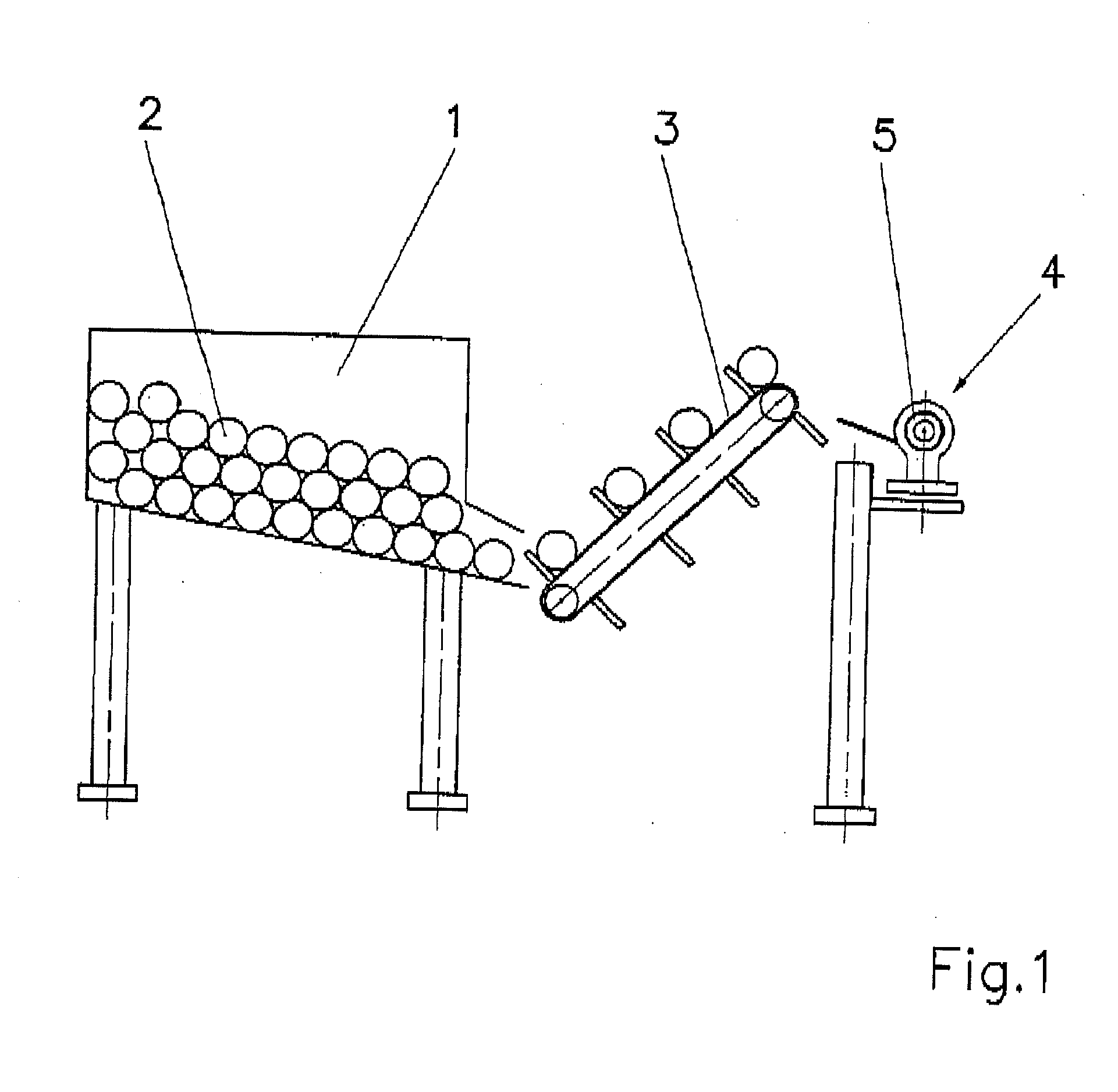
[0020]In a storage container 1, for example a magazine 1, large numbers of empty winding sleeves 2 are stacked such that the axes of rotation are parallel to the winding shaft 5. An endless conveyer belt 3, equipped with webs fastened transverse to its belt travel direction, successively grasps winding sleeves 2 from the magazine 1 and brings them into coaxial position toward the respective winding shaft 5. In this process the winding shaft 5 is floating at its free end 6, i.e., without support there, as is shown in FIG. 1.

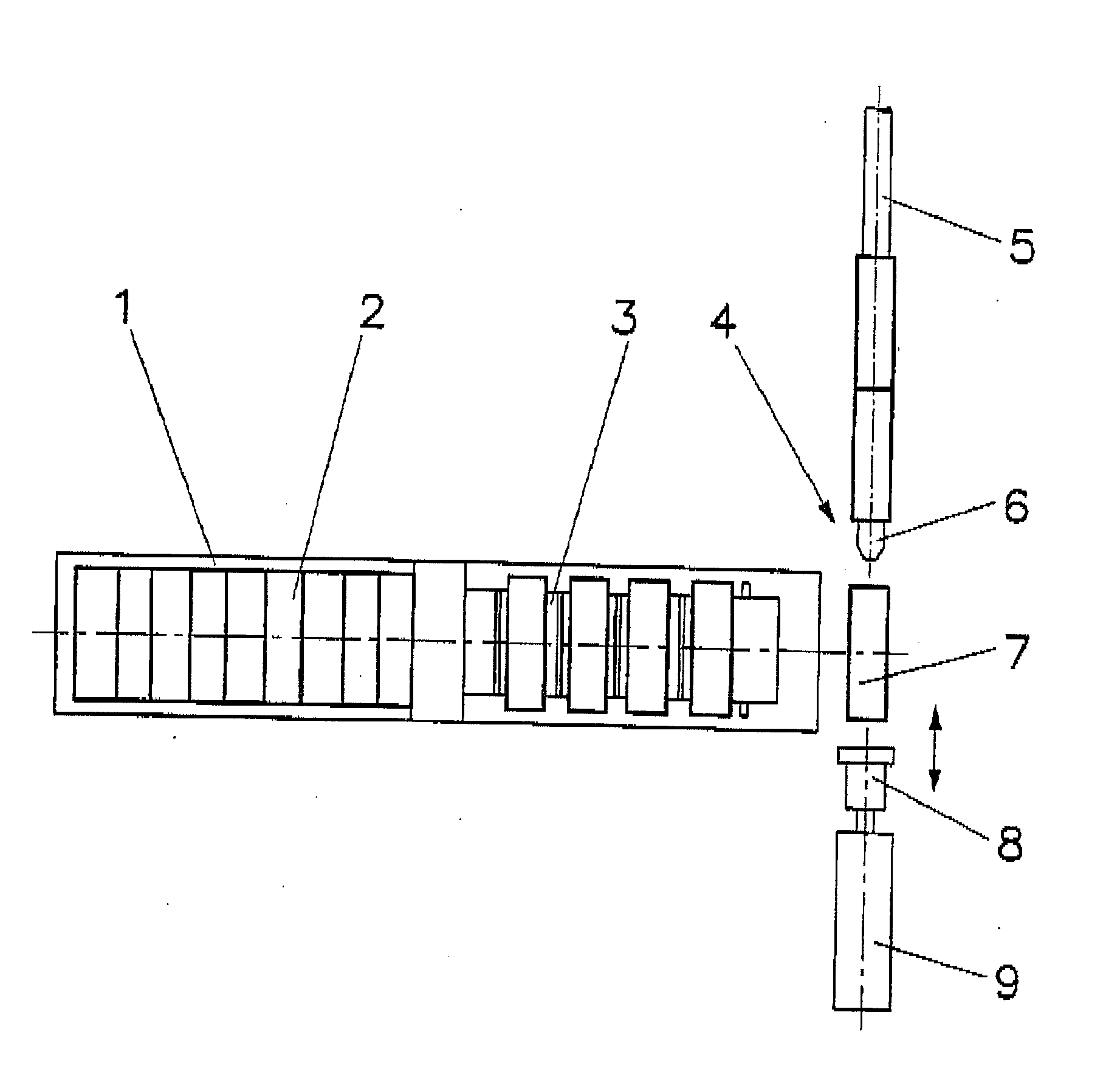
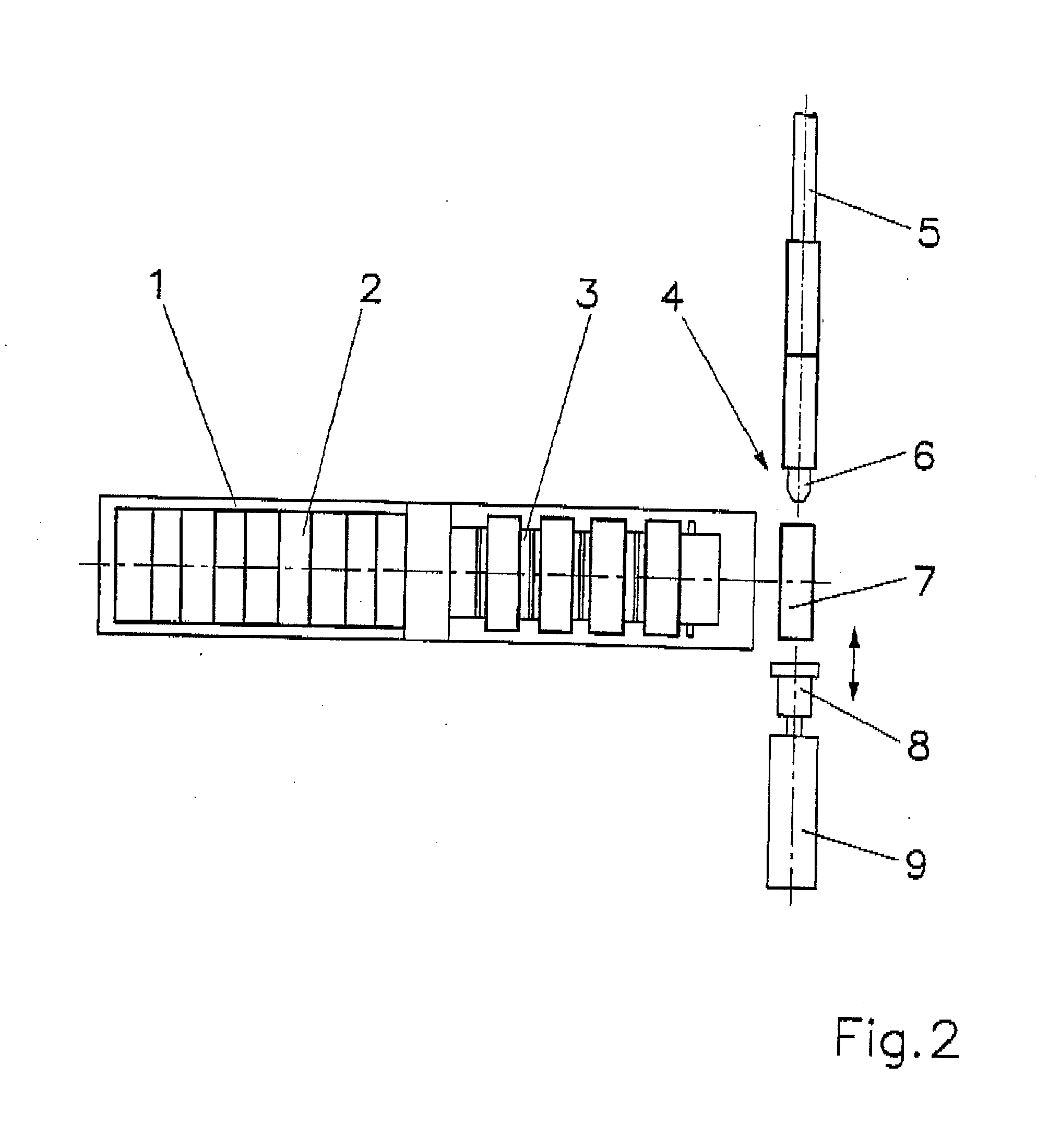
[0021]FIG. 2 shows a top view of the magazine 1, the conveyer belt 3, a winding shaft 5 and a sliding device 8 with a pneumatic cylinder 9. The empty winding sleeve 7 provided for filling-on is now directly adjacent to the free end of the winding shaft 5 in a coaxial position. The sliding device 8, for example a pneumatic cylinder or an electrically driven linear drive, now slides the winding sleeve 7 onto the winding shaft 5 and immediately withdraws again. Now t...


PUM


Abstract

A method for automatic sleeve filling of a winding shaft on roll cutting and winding machines is provided in which, in an exemplified embodiment, in a first step at least two empty winding sleeves are slid onto a free end of a winding shaft so that the winding sleeves are adjacent to one another, in a second step the last winding sleeve slid on by a freely positionable fork piece of a freely programmable draw-off plate along the winding shaft is slid over the winding shaft until the last winding sleeve has reached a predetermined position, in a third step the next-to-last winding sleeve slid on is grasped by tongs freely positionable along the winding shaft and is slid over the winding shaft to the point where in a fourth step the fork piece can dip into the gap produced by the tongs so that the next-to-last winding sleeve is positionable along the winding shaft by the fork piece.

Description

[0001]This nonprovisional application claims priority under 35 U.S.C. § 119(a) to German Patent Application No. DE 102007040643.8, which was filed in Germany on Aug. 27, 2007, and which is herein incorporated by reference.BACKGROUND OF THE INVENTION[0002]1. Field of the Invention[0003]The present invention relates to a process for automated sleeve filling of a winding shaft on roll slitting and winding machines.[0004]2. Description of the Background Art[0005]Roll slitting and winding machines are often equipped with two winding shafts, sometimes even more, on which winding sleeves are placed, corresponding to the width of the longitudinally slit strips. Often these winding sleeves are fastened onto friction rings that are supported by the winding shaft, moving with somewhat of a lead. This lead serves to compensate for length and diameter tolerances of the winding rolls. The fastening of the sleeves on the friction rings usually takes place, as in the case of free-wheeling, by clamp...

Claims


Application Information

Patent Timeline
IPC IPC(8): B65H67/06
CPCB65H19/2253B65H19/305B65H2301/41812B65H2301/41816B65H2301/41826B65H2301/4148B65H2408/236B65H2511/12B65H2301/41829B65H2220/04B65H2220/11
Inventor THIEL, ULRICHMULLER, WERNER
Owner SECAP GROUPE PITNEY BOWES S
Why Eureka
Try Eureka