Driving Device for Providing Light Dimming Control of Light-Emitting Element

a technology of light-emitting elements and driving devices, which is applied in the direction of electric variable regulation, process and machine control, instruments, etc., can solve the problems of achieve the effect of suppressing variation in luminance and chromaticity of light-emitting elements

Inactive Publication Date: 2009-03-05
ROHM CO LTD
View PDF6 Cites 15 Cited by
  • Summary
  • Abstract
  • Description
  • Claims
  • Application Information

AI Technical Summary

Benefits of technology

[0008]An object of the present invention is to provide a driving device that can suppress variation in the luminan...

Problems solved by technology

Therefore, this LED driving circuit is disadvanta...

Method used


Image

  • Driving Device for Providing Light Dimming Control of Light-Emitting Element
  • Driving Device for Providing Light Dimming Control of Light-Emitting Element
  • Driving Device for Providing Light Dimming Control of Light-Emitting Element

Examples


first embodiment

[0025][Configuration and Basic Operation]

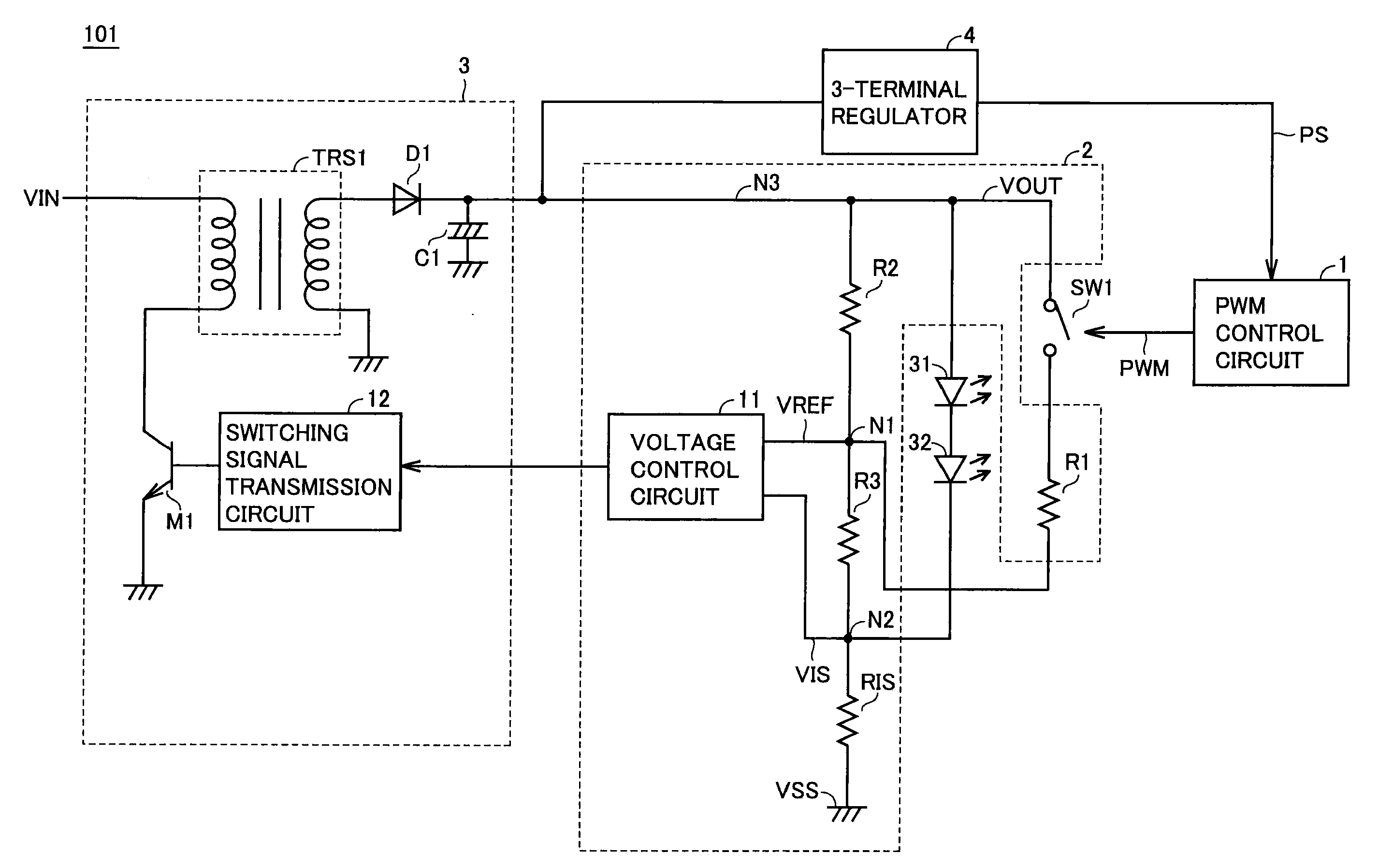
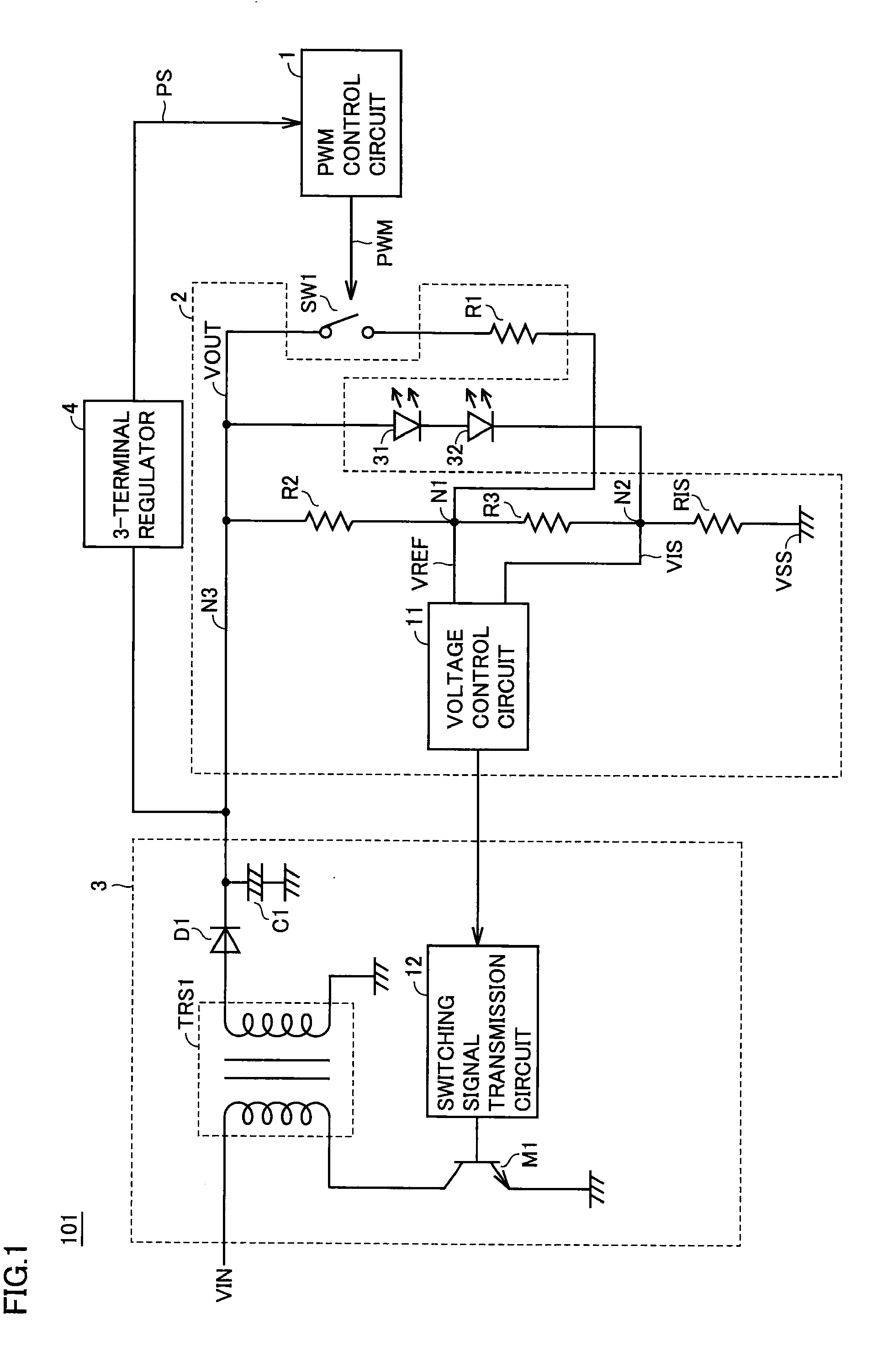
[0026]FIG. 1 is a functional block diagram of a configuration of a driving device according to a first embodiment of the present invention.

[0027]Referring to FIG. 1, a driving device 101 includes a PWM control circuit 1, a constant current control circuit 2, a voltage conversion circuit 3, a 3-terminal regulator (voltage conversion circuit) 4, LEDs 31 and 32, and a switch element SW1. Constant current control circuit 2 includes resistors R1, R2 and R3, a current setting resistor RIS, and a voltage control circuit 11. Voltage conversion circuit 3 includes a switching signal transmission circuit 12, a transistor (switch element) M1, a transformer TRS1, a diode D1, and a capacitor C1. Driving device 101 may be configured excluding LEDs 31 and 32. In other words, a configuration may be employed in which LEDs 31 and 32 are arranged outside driving device 101.

[0028]Switch element SW1 is, for example, a bipolar transistor, a MOS transistor, a relay,...

second embodiment

[0052]The present embodiment relates to a driving device with a light dimming function according to the ambient temperature, as compared to the driving device of the first embodiment. Elements other than those set forth below are similar to the driving device of the first embodiment.

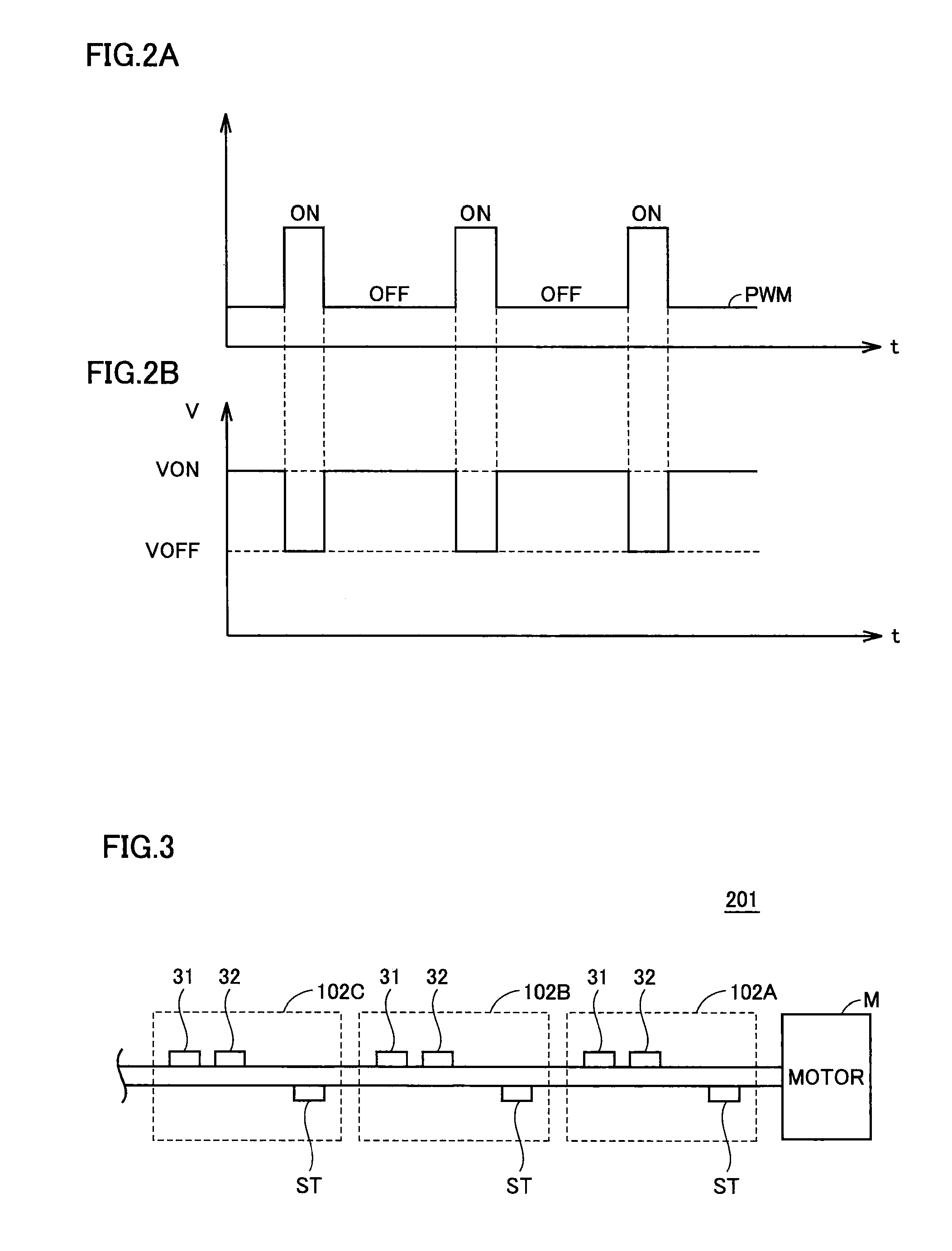
[0053]FIG. 3 represents a configuration of an illumination device according to a second embodiment of the present invention.

[0054]Referring to FIG. 3, an illumination device 201 includes a plurality of driving devices 102, and a motor M. In FIG. 3, three driving devices 102A, 102B and 102C, and a plurality of LEDs, corresponding to each driving device 102, are shown as a representative example.

[0055]By the heat generated from motor M, LEDs 31 and 32 in a driving device 102A located closest to motor M attain a high temperature. Accordingly, color unevenness will occur at illumination device 201 since the luminance and chromaticity becomes higher as compared to those of the LEDs in other driving devices 10...


PUM


Abstract

A driving device includes a first switch element to switch between applying or not applying to a light-emitting element a voltage directed to setting the light-emitting element in an ON state, and a constant current control circuit to adjust a current flowing through the light-emitting element when the light-emitting element is in an ON state to a predetermined current value.

Description

BACKGROUND OF THE INVENTION[0001]1. Field of the Invention[0002]The present invention relates to driving devices, particularly a driving device for providing light dimming control of a light-emitting element.[0003]2. Description of the Background Art[0004]Illumination devices such as incandescent lamps and streetlight employing light-emitting elements such as an LED (Light Emitting Diode) are developed.[0005]As a method of adjusting the light of a light-emitting element, PWM (Pulse Width Modulation) control of the luminance of an LED is known. This method is directed to adjusting the luminance of an LED by altering the pulse width (time width) of the current flowing through the LED, i.e. by altering the duty of the pulse of the current flowing through the LED.[0006]For example, Japanese Patent Laying-Open No. 2006-324671 (Patent Document 1) discloses an LED driving circuit set forth below. The LED driving circuit includes a PWM driving unit providing a switching pulse having the wid...

Claims


Application Information

Patent Timeline
IPC IPC(8): H05B41/36
CPCH05B33/0815Y02B20/347H05B33/0818H05B45/382Y02B20/30
Inventor FUKUI, HIROYUKIKITAGA, KAZUAKI
Owner ROHM CO LTD
Why Eureka
Try Eureka