Current Detector Unit And Motor Control Device

a current detector and motor control technology, applied in the direction of electronic commutators, dynamo-electric converter control, instruments, etc., can solve the problems of increasing the overall cost of a system incorporating the motor, unable and inability to detect two phase currents

Active Publication Date: 2009-03-05
III HLDG 12 LLC
View PDF7 Cites 33 Cited by
  • Summary
  • Abstract
  • Description
  • Claims
  • Application Information

AI Technical Summary

Benefits of technology

[0019]The significance and effect of the present invention will become more apparent from the following detailed description of preferred embodiments thereof. It is to be understood that the significance of the present invention and the significance of terms describing the component elements thereof are not limited in any way by those specifically described in the embodiments below, because those embodiments are merely examples of how the invention can be implemented.

Problems solved by technology

However, the use of two current sensors undesirably increases overall cost of a system incorporating the motor.
However, if the voltage levels of the maximum phase and intermediate phase come close to each other, or the voltage levels of the minimum phase and intermediate phase come close to each other, it becomes impossible to detect two phase currents.
However, with this conventional method, since the voltage threshold value has to be set with allowance made for various factors, there is a possibility that, although in actuality two phase currents can be detected, it is judged that they cannot be detected.

Method used


Image

  • Current Detector Unit And Motor Control Device
  • Current Detector Unit And Motor Control Device
  • Current Detector Unit And Motor Control Device

Examples


example 1

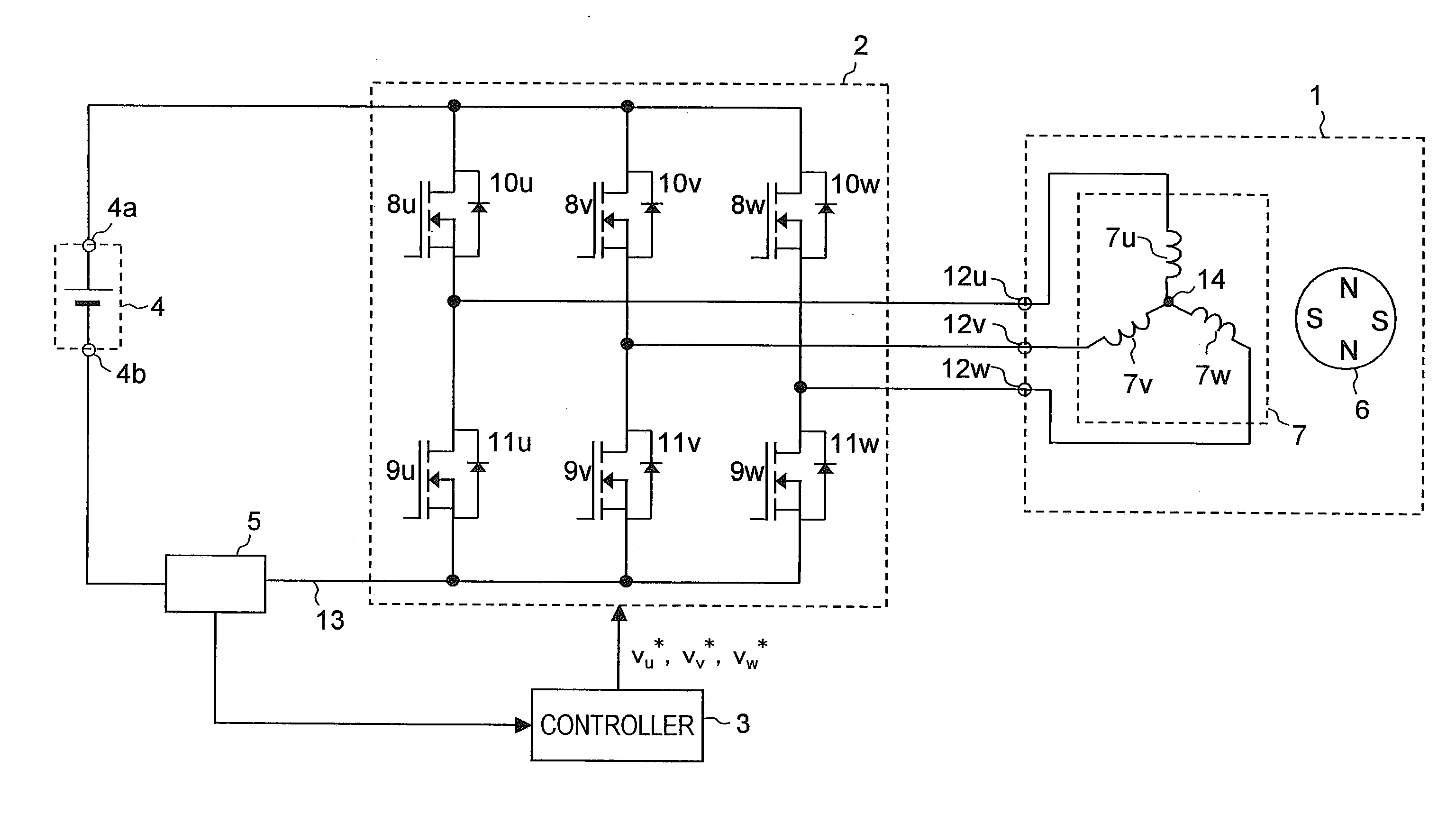
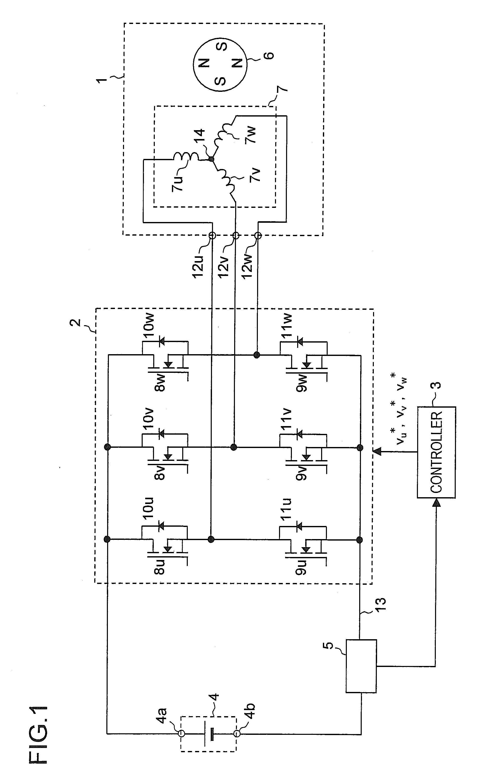
[0110]First, Example 1 will be described. FIG. 12 is a block diagram of a motor drive system according to Example 1. The motor drive system shown in FIG. 12 includes a controller 3a, in addition to the motor 1, the inverter 2, the direct-current power supply 4, and the current sensor 5, which have been shown in FIG. 1. The controller 3a is a specific example of the controller 3 shown in FIG. 1, and realizes the functions of the controller 3. The controller 3a includes different parts represented by reference numerals 21 to 26. The different parts constituting the motor drive system can freely use all the values produced within the motor drive system as necessary.

[0111]Before presenting a detailed description of the different parts of the motor drive system shown in FIG. 12, different state quantities (state parameters) will be described and defined. FIG. 13 is an analysis model diagram of the motor 1. FIG. 13 shows the U-phase, V-phase, and W-phase armature winding fixed axes. Refer...

example 2

[0156]Example 1 deals with the motor drive system in which vector control is performed such that the axis error Δθ between the d- and γ-axes is made to converge to zero, that is, such that the γ-axis is made to follow the d-axis; however, Example 1 may be modified to be Example 2 in which vector control is performed such that the γ-axis is made to follow an axis other than the d-axis. For example, by defining a dm-axis described in the treatise titled “Position Sensorless Vector Control for Permanent Magnet Synchronous Motors Based on Maximum Torque Control Frame” by Hida et al.; published by the Industry Applications Society of the Institute of Electrical Engineers of Japan; included in the Collection of the Lecture Treatises Presented at the 2006 Annual Conference of the Industry Applications Society of the Institute of Electrical Engineers of Japan; pp. 385-388 (I-385-I-388); August 2006, vector control may be performed such that the γ-axis is made to follow the dm-axis.

[0157]The...

example 3

[0159]Examples 1 and 2 deal with the motor drive systems in which position sensorless vector control is performed that uses no position sensor for detecting the rotor position. However, the techniques described in Examples 1 and 2 are useful in a case where the position sensor is provided. As Example 3 of the invention, a description will be given below of a motor drive system provided with the position sensor. In a case where the position sensor is provided, the motor drive system of Example 1 (or 2) may be modified as follows.

[0160]The estimator 26 is removed from the motor drive system shown in FIG. 12. The phase of the d-axis detected by the position sensor is treated as θe, and is fed to the coordinate converters 22 and 25. Here, θe is, ideally, equal to 0 shown in FIG. 13. In addition, Oe based on the detection of the position sensor is differentiated by a differentiator (unillustrated) for speed calculation to obtain ωe, and θe thus obtained is fed to the speed controller 23....


PUM


Abstract

A current detector unit has a current detecting portion detecting a current flowing between a three-phase inverter and a direct-current power supply as a detection current; a three-phase current detecting portion for detecting a three-phase current of the inverter based on the detection current; and a judging portion judging, based on the detection current, whether or not a target time point belongs to a period during which the three-phase current can be detected. If the judging portion judges that the target time point belongs to the period, the three-phase current detecting portion detects the three-phase current.

Description

[0001]This nonprovisional application claims priority under 35 U.S.C. §119(a) on Patent Application No. 2007-221981 filed in Japan on Aug. 29, 2007, the entire contents of which are hereby incorporated by reference.BACKGROUND OF THE INVENTION[0002]1. Field of the Invention[0003]The present invention relates to current detector units for detecting a current and to motor control devices that drive and control a motor.[0004]2. Description of Related Art[0005]In order to perform vector control of a motor by supplying three-phase alternating-current power to the motor, it is necessary to detect two phase currents (for example, a U-phase current and a V-phase current) among three phase currents consisting of U-phase, V-phase, and W-phase currents. In general, detection of two phase currents is performed by using two current sensors (such as current transformers). However, the use of two current sensors undesirably increases overall cost of a system incorporating the motor.[0006]It is for ...

Claims


Application Information

Patent Timeline
Patent Type & Authority Applications(United States)
IPC IPC(8): H02P27/06G01R19/00H02M7/48H02P6/06H02P6/08H02P6/16H02P6/17H02P6/28H02P21/00H02P21/18H02P21/22H02P21/24H02P21/28H02P23/16H02P27/08
CPCG01R19/0046G01R19/2506H02M2001/0009H02M7/5395H02P21/0039H02P21/24H02M1/0009
Inventor YAMAMOTO, SHINYA
Owner III HLDG 12 LLC
Why Eureka
Try Eureka