Power switching apparatus and method of controlling the same

a power switch and power switch technology, applied in circuit-breaking switches, circuit-breaking switches for excess current, relays, etc., can solve the problems of circuit breaker cost and size increase, difficulty in simplifying the switch driving mechanism, and re-ignition

Active Publication Date: 2009-03-05
MITSUBISHI ELECTRIC CORP
View PDF8 Cites 21 Cited by
  • Summary
  • Abstract
  • Description
  • Claims
  • Application Information

AI Technical Summary

Benefits of technology

[0008]It is an object of the present invention to at least partially solve the problems in the conventional technology.

Problems solved by technology

A power switching device, such as a circuit breaker, has a problem that reignition occurs during operation of breaking a small capacitive current, such as a charging current in an unloaded power line or a load current in a capacitor bank.
Therefore, the circuit breaker is necessitated to be of complex configuration, making it difficult to simplify the switch driving mechanism.
Furthermore, because a large force is applied to the coupling mechanism during operation, the cam mechanism needs to be composed of rigid members, and thereby the cost and the size of the circuit breaker increase.

Method used


Image

  • Power switching apparatus and method of controlling the same
  • Power switching apparatus and method of controlling the same
  • Power switching apparatus and method of controlling the same

Examples


Embodiment Construction

[0017]Exemplary embodiments of the present invention are explained in detail below with reference to the accompanying drawings.

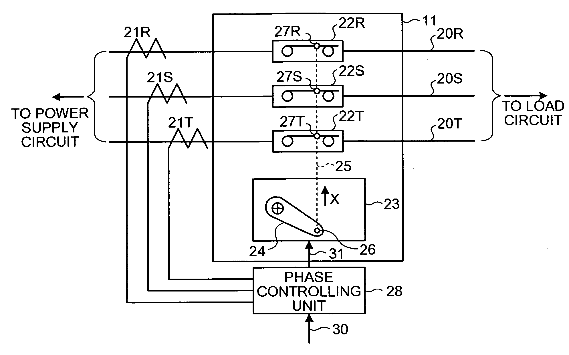
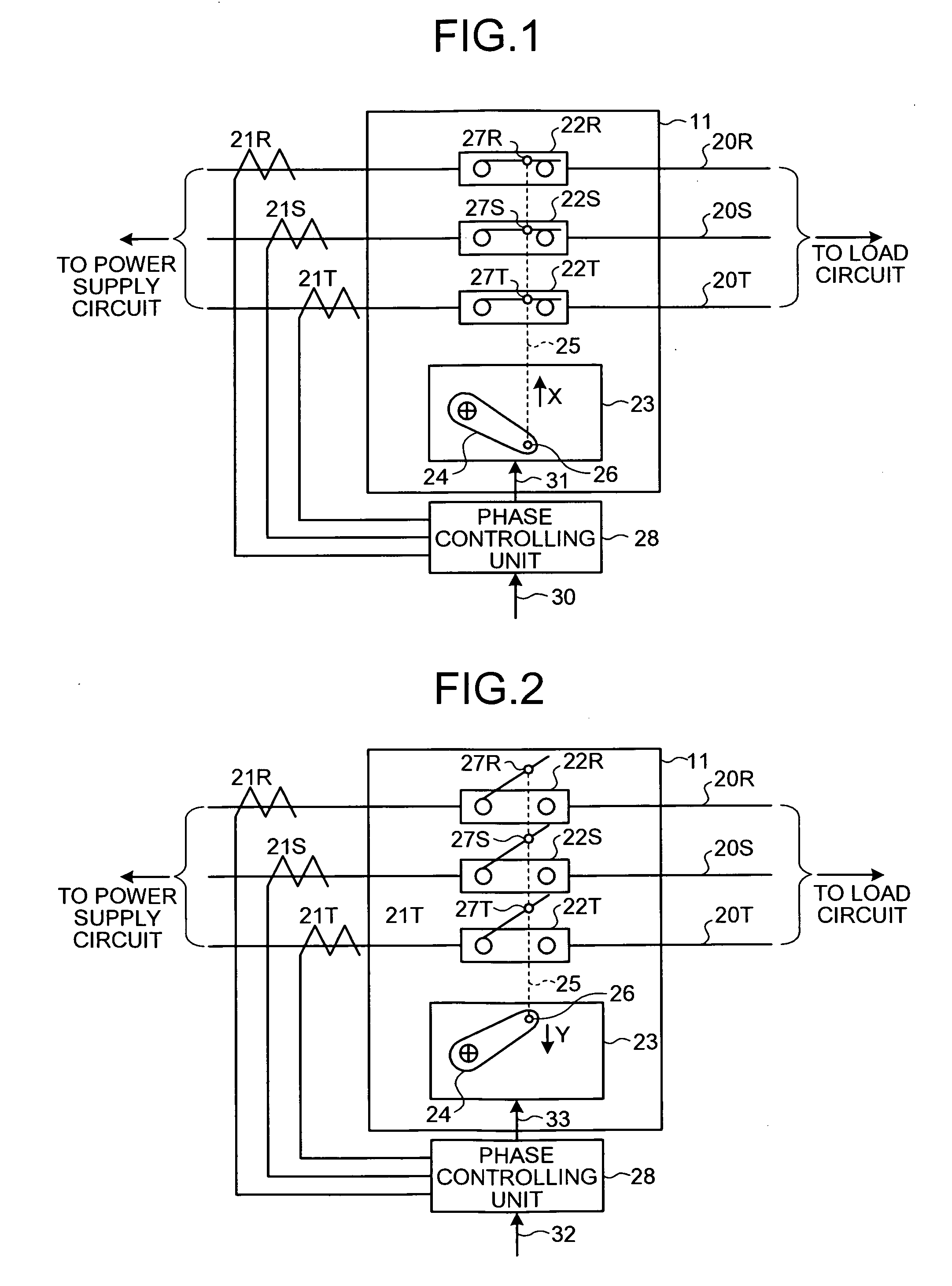
[0018]FIG. 1 is a schematic diagram of a power switching apparatus according-to an embodiment of the present invention. The power switching apparatus includes a circuit breaker (hereinafter, “breaker”) 11 and a phase controlling unit 28. The breaker 11 is on three power lines 20R, 20S, and 20T that connect between a load circuit and a power-supply circuit that supplies driving power to the load circuit. The phase controlling unit 28 is, e.g., a microprocessor, and controls the ON / OFF position of the breaker 11. Current measuring units 21R, 21S, and 21T are arranged on the power lines 20R, 20S, and 20T, respectively, on the side of the power-supply circuit. The current measuring units 21R, 21S, and 21T measure currents flowing in three phases of the power lines 20R, 20S, and 20T, respectively. The phase controlling unit 28 performs such operations as controll...


PUM


Abstract

A power switching apparatus includes a breaker unit, an operating unit, a measuring unit, and a controlling unit. The breaker unit is connected on a three-phase current line, and includes switches each corresponding to one of phases of the three-phase current line. The operating unit simultaneously turns on or off the switches. The measuring unit measures a current flowing in each phase, and determines a time point where current flowing in one of the phases becomes zero as a reference time point. The controlling unit controls, when interrupting load current, the operating unit to turn off the switches in a range from 20 degrees to 40 degrees of an electric angle from the reference time point.

Description

BACKGROUND OF THE INVENTION[0001]1. Field of the Invention[0002]The present invention relates to a technology for control of power switch.[0003]2. Description of the Related Art[0004]A power switching device, such as a circuit breaker, has a problem that reignition occurs during operation of breaking a small capacitive current, such as a charging current in an unloaded power line or a load current in a capacitor bank. One conventional approach for preventing such reignition is to operate the power switching device at high speed before the recovery voltage reaches its crest value, i.e., for approximately 10 milliseconds, when the power switching device interrupts current. As a result, insulation recovery can be achieved before the recovery voltage rises.[0005]For example, Japanese Patent Application Laid-open No. 2004-55420 discloses a conventional circuit breaker in which a movable contact is coupled to a switch driving mechanism through a cam mechanism, which moves the movable cont...

Claims


Application Information

Patent Timeline
Patent Type & Authority Applications(United States)
IPC IPC(8): H01H83/00
CPCH01H33/593H01H9/563
Inventor MORI, TOMOHITOKOYAMA, HARUHIKO
Owner MITSUBISHI ELECTRIC CORP
Why Eureka
Try Eureka