Antenna device, electronic device and antenna cover

a technology of electronic devices and antenna covers, applied in the field of antenna devices, can solve the problems of limited installation space, difficult to provide enough thickness and area to achieve the desired directivity, and difficult to apply the technique to the antenna device mounted in portable devices in terms of installation space, etc., to suppress the increase in installation space and strong directivity

Inactive Publication Date: 2009-03-05
FUJITSU CLIENT COMPUTING LTD
View PDF7 Cites 161 Cited by
  • Summary
  • Abstract
  • Description
  • Claims
  • Application Information

AI Technical Summary

Benefits of technology

[0029]As described above, according to the present invention, it is possible to provide an antenna device capable of obtaining a strong directivity easily toward the horizontal direction while suppressing the increase

Problems solved by technology

However, a space for the installation is limited in most antenna devices mounted in a portable device, for example, such as a wireless LAN antenna device or the like that is mounted in a note PC.
Therefore, it is difficult to provide enough thickness and area capable of obtaining a desired directivity for the cover wrapping the antenna, by applying the techniques shown in the Patent Application Publication Nos. 2001-244716 and 2004-15408.
Moreover, according to the technique

Method used


Image

  • Antenna device, electronic device and antenna cover
  • Antenna device, electronic device and antenna cover
  • Antenna device, electronic device and antenna cover

Examples


Embodiment Construction

[0064]The embodiments of the present invention will be described below with reference to the drawings.

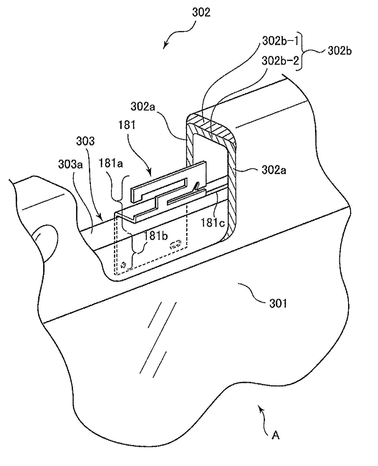
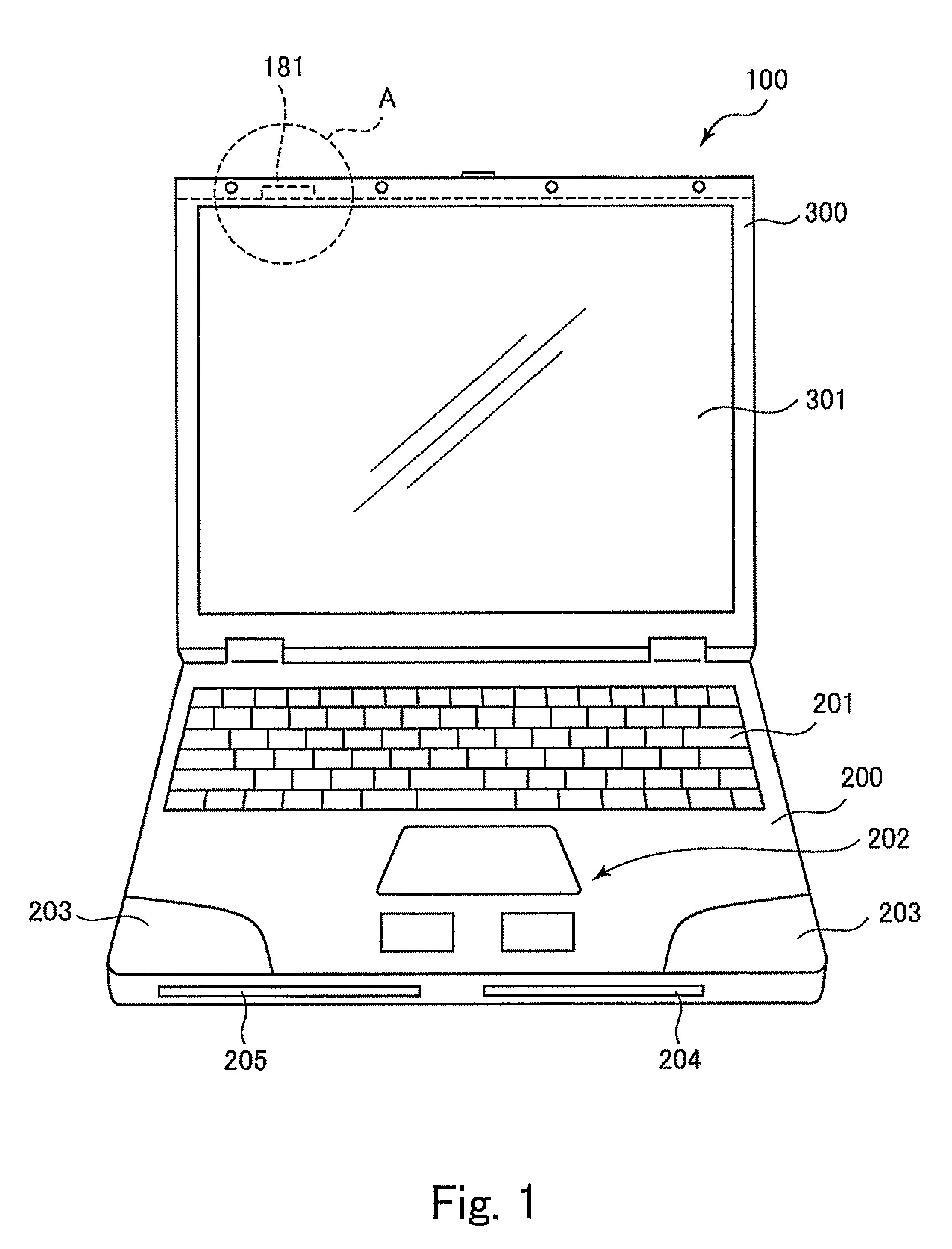
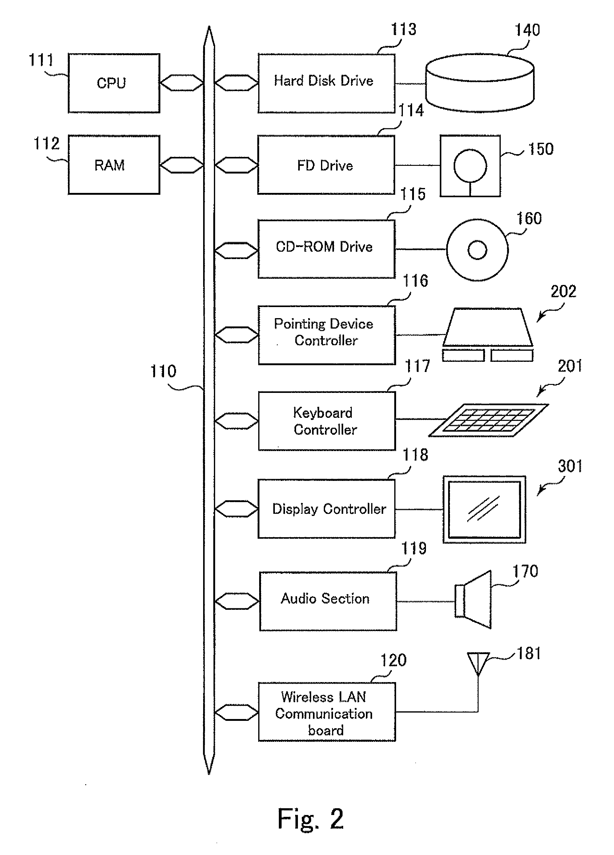
[0065]FIG. 1 is a drawing of the outlook of a notebook type personal computer (note PC) as one embodiment of the present invention, and FIG. 2 is a drawing of a hardware configuration of the note PC.

[0066]Here, this note PC 100 corresponds to one embodiment of the electronic device according to the present invention.

[0067]This note PC 100 includes a main body 200 having an undersurface to mount the note PC 100 thereon, and a top section 300 that can be opened and closed freely relative to the main body 200. The top section 300 is closed when this note PC 100 is not used and opened when used.

[0068]FIG. 1 shows a state of this note PC 100 in use.

[0069]The main body 200 is equipped with a keyboard 201, a pointing device 202, a sound section 203 incorporating a speaker inside, a FD slot 204 through which a flexible disk (FD) is inserted, a CD-ROM slot 205 through which a CD-ROM or the l...


PUM


Abstract

An antenna device is mounted in a note PC and is used for communication between the note PC and the external of the note PC. The antenna device is provided with an antenna for wireless LAN for transmitting and receiving radio waves, and a cover. The cover is formed of a dielectric material for covering the antenna with a wall and a ceiling, and strengthens the directivity of radio wave communication on the wall side of the antenna device by a double layer structure of the ceiling that is thicker than the wall.

Description

TECHNICAL FIELD[0001]The present invention relates to an antenna device used for radio wave communication, an electronic device mounted with such an antenna device and an antenna cover used for such an antenna device.BACKGROUND ART[0002]A technique for building a so-called LAN (Local Area Network) by connecting multiple computers one another with cables has become widespread in offices or the like. Here, in the technique for building a LAN with cables, there are such problems that a construction of cable installation often takes time and cost and in some places or a LAN cannot be built due to the difficulty of cable installation or the like. Furthermore, in recent years, a notebook type personal computer (note PC) convenient for carrying around is often used, yet if the note PC is incorporated into a LAN built with cables, there is a problem that the convenience of portability of the note PC is impaired or the like.[0003]Therefore, recently, there is an increasing demand for a so-ca...

Claims


Application Information

Patent Timeline
IPC IPC(8): H01Q1/24H01Q1/42
CPCG06F1/1616G06F1/1698H01Q9/42H01Q1/241H01Q1/422H01Q1/2266
Inventor KONISHI, MICHIHIRO
Owner FUJITSU CLIENT COMPUTING LTD
Why Eureka
Try Eureka