Complex elements for antenna of radio frequency repeater and dipole array circular polarization antenna using the same

a technology of dipole arrays and repeaters, applied in the direction of polarised antenna unit combinations, antenna feed intermediates, antennas, etc., can solve the problems of reducing the frequency of propagation, rf repeaters being oscillated, and the inability to receive a radio frequency (rf) from a mobile terminal, so as to achieve a wide beam width and minimize interference. the effect of main lobe and side lobes

Inactive Publication Date: 2009-03-05
ONOHAKOBI TECH INST CO LTD
View PDF4 Cites 18 Cited by
  • Summary
  • Abstract
  • Description
  • Claims
  • Application Information

AI Technical Summary

Benefits of technology

[0022]The present invention provides complex elements for an antenna of a radio frequency (RF) repeater in which interference due to a main lobe and side lobes can be minimized and in which a feeding method by which impedance matching and occurrence of circular polarization are simultaneously achieved with a relatively large beam width, is used, and a dipole array circular polarization antenna using the same.

Problems solved by technology

In a wireless network of a mobile communication system, due to nature and artificial obstacles such as mountains or buildings, tunnels, insides of buildings, etc., the intensity of propagation is reduced, and a shadow region in which reception of a radio frequency (RF) from a mobile terminal is not possible, is formed.
The RF repeater is oscillated and a normal operation cannot be performed.
Thus, the gain of the amplifier is about 40-55 dB, which limits a basic function of the repeater, i.e., a function of expanding a sufficient coverage or supplementing the shadow region and acts the greatest disadvantage of the RF repeater.
In this case, the main lobe and the side lobes that are directly reflected by ambient buildings or objects are vertically radiated in opposite direction to radiation direction, and interference occurs.
As such, the size of the antenna increases and manufacturing costs thereof increase.

Method used


Image

  • Complex elements for antenna of radio frequency repeater and dipole array circular polarization antenna using the same
  • Complex elements for antenna of radio frequency repeater and dipole array circular polarization antenna using the same
  • Complex elements for antenna of radio frequency repeater and dipole array circular polarization antenna using the same

Examples


Embodiment Construction

[0047]Hereinafter, the present invention will be described in detail by explaining exemplary embodiments of the invention with reference to the attached drawings.

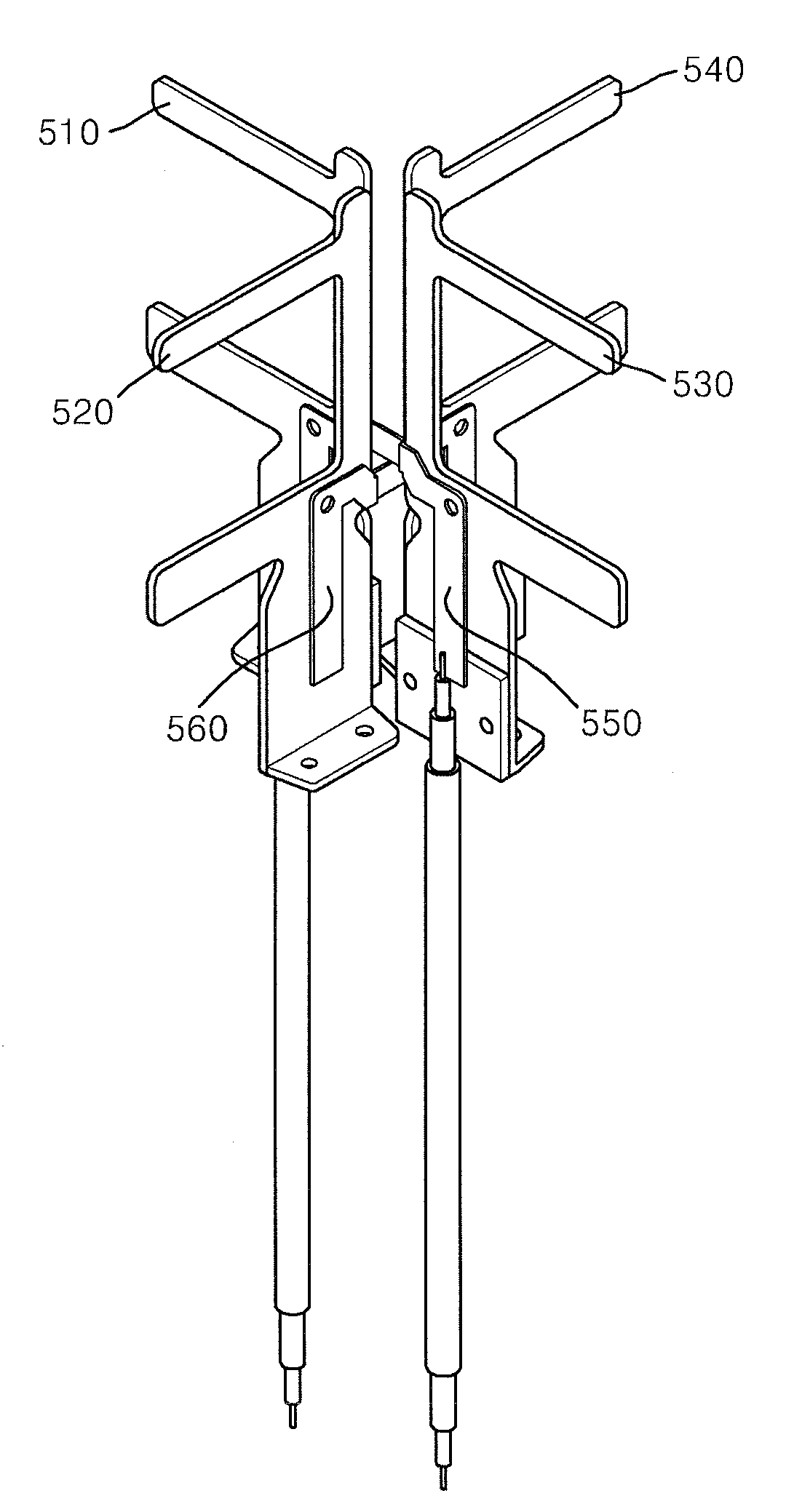
[0048]FIG. 5 illustrates the structure of complex elements 500 for an antenna of a radio frequency (RF) repeater according to an embodiment of the present invention, and FIGS. 6A through 6C illustrate the detailed structure of components of the complex elements for the antenna of the RF repeater.

[0049]Referring to FIGS. 5 through 6C, the complex elements 500 for the antenna of the RF repeater according to the current embodiment of the present invention comprises first through fourth radiation members 510, 520, 530, and 540 and first and second feeding members 550 and 560.

[0050]Each of the first through fourth radiation members 510, 520, 530, and 540 has same shape. As an example, the first radiation member 510 comprises a radiation portion 610 and a leg portion 620. The radiation portion 610 comprises a pair of parallel por...


PUM


Abstract

Provided are complex elements for an antenna of a radio frequency repeater and a dipole array circular polarization antenna using the same. The complex elements for the antenna of the RF repeater include: a plurality of radiation members which are separated from one another by a predetermined angular distance and has a radiation portion and a leg portion, the radiation portion comprising a pair of parallel portions, which are separated from each other in a vertical direction and are disposed to be parallel to each other, and a connection portion, which is disposed to be perpendicular to the pair of parallel portions and connects ends of each of the pair of parallel portions, and the leg portion extending from the radiation portion; and a plurality of feeding members, each of the feeding members connected to each of the radiation members that face each other, among the plurality of radiation members.

Description

CROSS-REFERENCE TO RELATED PATENT APPLICATION[0001]This application claims the benefit of Korean Patent Application No. 10-2007-0086466, filed on Aug. 28, 2008, in the Korean Intellectual Property Office, the disclosure of which is incorporated herein in its entirety by reference.BACKGROUND OF THE INVENTION[0002]1. Field of the Invention[0003]The present invention relates to complex elements for an antenna of a radio frequency (RF) repeater and a dipole array circular polarization antenna using the same, and more particularly, to complex elements for an antenna that is used in a radio frequency (RF) repeater system and that generates circular polarization, and a dipole array circular polarization antenna using the same.[0004]2. Description of the Related Art[0005]In a wireless network of a mobile communication system, due to nature and artificial obstacles such as mountains or buildings, tunnels, insides of buildings, etc., the intensity of propagation is reduced, and a shadow regio...

Claims


Application Information

Patent Timeline
Patent Type & Authority Applications(United States)
IPC IPC(8): H01Q21/08H01Q9/16
CPCH01Q9/26H01Q21/26H01Q21/08H01Q21/062
Inventor LEE, EUNG-HYUNKIM, CHEOL-HOOYOON, YOUNG-CHAN
Owner ONOHAKOBI TECH INST CO LTD
Why Eureka
Try Eureka