
Laser system for target metrology and alteration in an EUV light source

A technology of laser system and optical system, applied in the direction of optics, optomechanical equipment, X-ray tube with huge current, etc., can solve problems such as difficulties

Pending Publication Date: 2021-05-07
ASML NETHERLANDS BV
View PDF6 Cites 2 Cited by
  • Summary
  • Abstract
  • Description
  • Claims
  • Application Information

AI Technical Summary

Problems solved by technology

In practice, this can be very difficult

Method used


Image

  • Laser system for target metrology and alteration in an EUV light source
  • Laser system for target metrology and alteration in an EUV light source
  • Laser system for target metrology and alteration in an EUV light source

Examples


Embodiment Construction

[0035] Various embodiments are now described with reference to the drawings, wherein like reference numerals are used to refer to like elements throughout. In the following description, for purposes of explanation, numerous specific details are set forth in order to facilitate a thorough understanding of one or more embodiments. However, it may be apparent in some or all cases that any of the embodiments described below may be practiced without employing the specific design details described below.

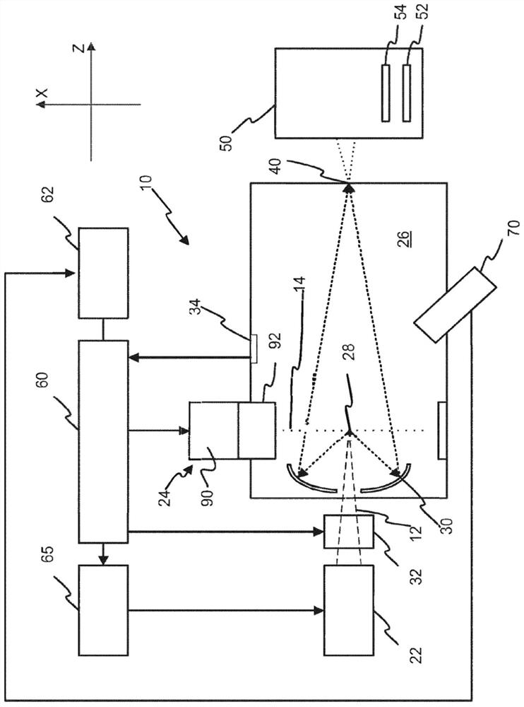
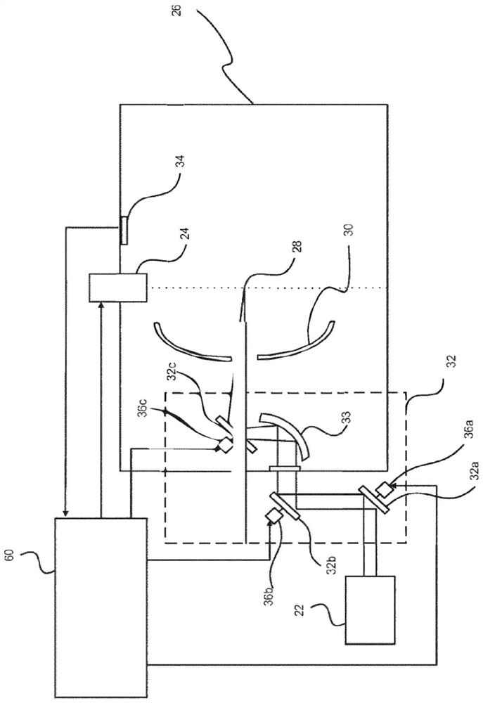
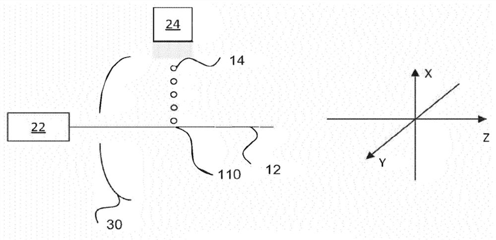
[0036] first reference figure 1 , figure 1 A schematic diagram of an exemplary EUV radiation source (eg, laser-produced plasma EUV radiation source 10 ) is shown in accordance with an aspect of embodiments of the present invention. As shown, the EUV radiation source 10 can include a pulsed or continuous laser source 22, which can be, for example, a pulsed gas discharge CO 2 A laser source that produces a radiation beam 12 having a wavelength typically below 20 μm, for example...


PUM


Abstract

Disclosed is a system and method for generating EUV radiation in which a laser is used in a multistage process to illuminate without altering a target material and then irradiate the target material to alter a target material with the illumination stage being used to determine the timing for firing during the irradiation stage or stages.

Description

[0001] Cross References to Related Applications [0002] This application claims priority to US Application 62 / 736,012, filed September 25, 2018, the entire contents of which are hereby incorporated by reference. technical field [0003] The present disclosure relates to light sources that generate extreme ultraviolet light through excitation of target materials, and in particular to the measurement (eg, detection) and modification (eg, preparation and / or ionization) of target materials in such sources. Background technique [0004] Extreme ultraviolet ("EUV") light (e.g., electromagnetic radiation with a wavelength of about 50 nm or shorter (sometimes referred to as soft X-rays), including light with a wavelength of about , silicon wafers) to produce extremely small features. [0005] Methods for generating EUV light include, but are not limited to, changing the physical state of the target material to a plasma state. Target materials include elements with emission lines...

Claims


Application Information

Patent Timeline
Patent Type & Authority Applications(China)
IPC IPC(8): H05G2/00
CPCH05G2/008G03F7/70025G03F7/70033G03F7/70041G03F7/70133G03F7/70558
Inventor R·J·拉法克I·V·福门科夫
Owner ASML NETHERLANDS BV
Learn More