Lens barrel and imaging apparatus

Inactive Publication Date: 2009-03-05
SONY CORP
View PDF8 Cites 10 Cited by
  • Summary
  • Abstract
  • Description
  • Claims
  • Application Information

AI Technical Summary

Benefits of technology

[0011]In the lens barrel and the imaging apparatus according to an embodiment of the invention, it is possib

Problems solved by technology

That is, the size of the zoom lens cannot be sufficiently reduced because the zo

Method used


Image

  • Lens barrel and imaging apparatus
  • Lens barrel and imaging apparatus
  • Lens barrel and imaging apparatus

Examples


Example

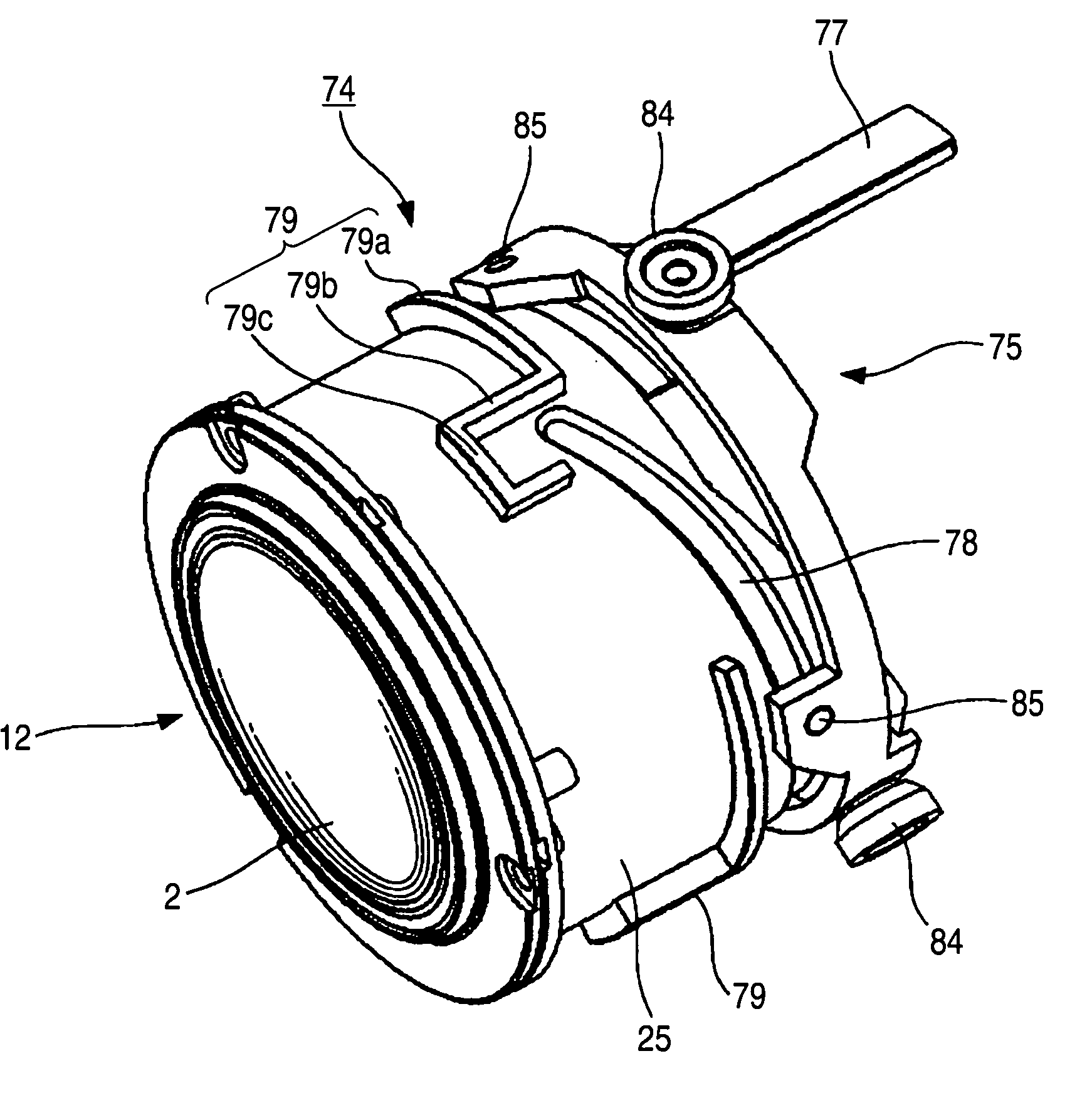
[0051]Providing the position restrictor that can engage the fitting raised portion on the focus cam ring and forming the position restrictor with the rotational-direction restrictor and the optical axis-direction restrictor allow a simply configured lens barrel and imaging apparatus to contribute to reduction in the size and improvement in the optical performance.

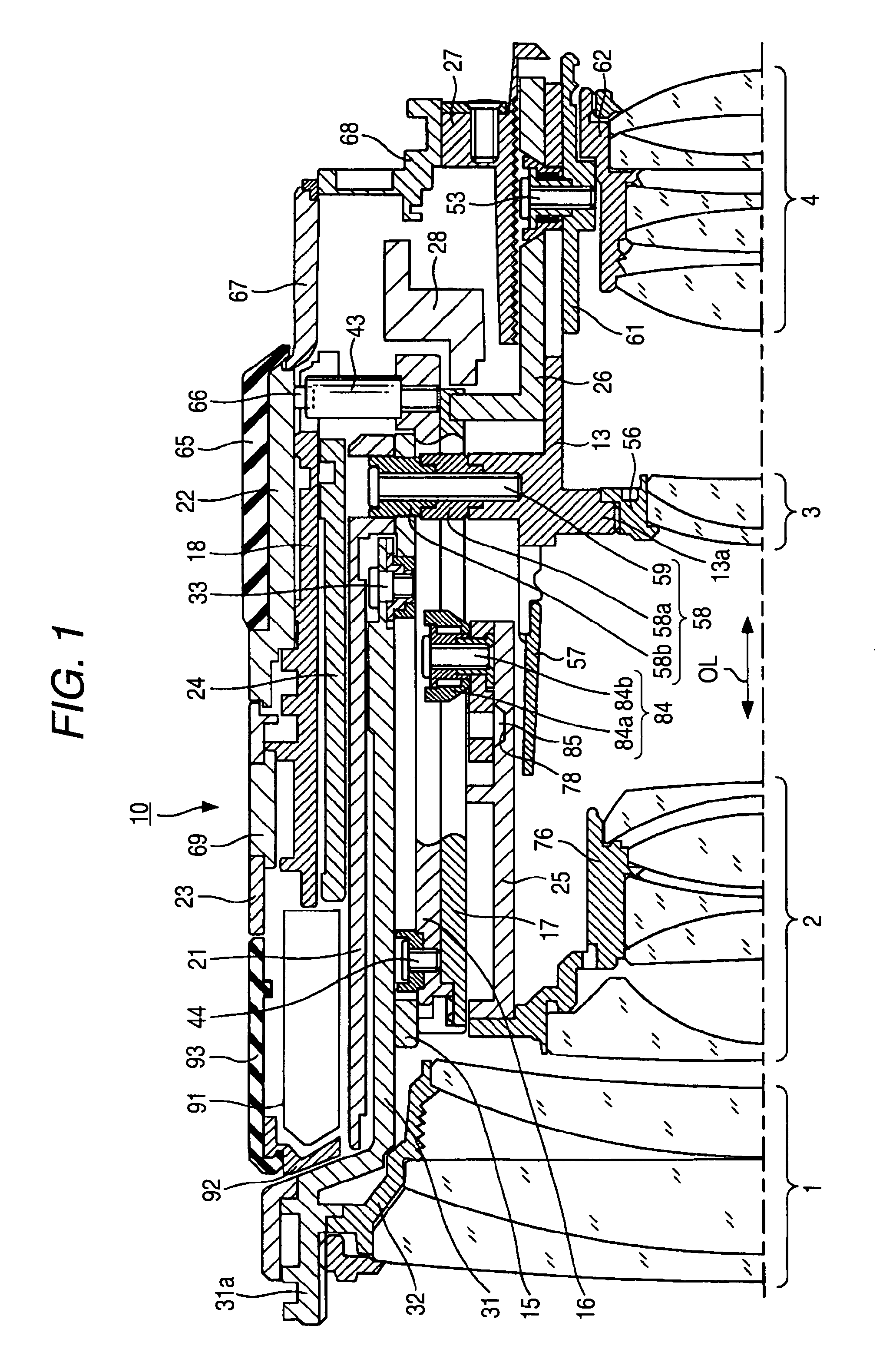
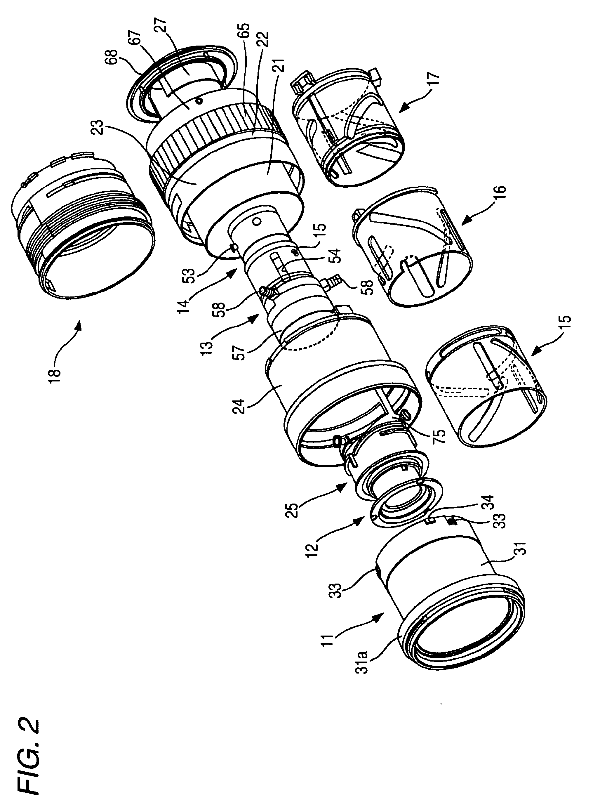
[0052]An embodiment of the invention will be described with reference to the accompanying drawings. FIGS. 1 to 39 explain an example of the embodiment of the invention. That is, FIG. 1 is a cross-sectional view showing a first example of a lens barrel according to the embodiment of the invention. FIG. 2 is a perspective exploded view. FIGS. 3A and 3B are perspective views of a first-group frame. FIG. 4 is a perspective view of a first-group cam ring. FIG. 5 is a perspective view of a zoom cam ring. FIG. 6 is the development of the first-group cam ring. FIG. 7 is the development of the zoom cam ring. FIG. 8 is a perspective ...


PUM


Abstract

A lens barrel includes a focus cam ring that holds a focus lens group and moves in the optical axis direction of the focus lens group while rotating along a cam groove in response to a focusing operation, and a fixed tube having a fitting raised portion that can pivot the focus cam ring in the rotational direction thereof and movably supports the focus cam ring in the optical axis direction. The focus cam ring has a position restrictor that can engage the fitting raised portion, and the position restrictor includes a rotational-direction restrictor that restricts the position of the focus cam ring in the rotational direction and an optical axis-direction restrictor that restricts the position of the focus cam ring in the optical axis direction.

Description

CROSS REFERENCES TO RELATED APPLICATIONS[0001]The present invention contains subject matter related to Japanese Patent Application JP 2007-229478 filed in the Japanese Patent Office on Sep. 4, 2007, the entire contents of which being incorporated herein by reference.BACKGROUND OF THE INVENTION[0002]1. Field of the Invention[0003]The present invention relates to a lens barrel for a zoom lens and other lenses, and an imaging apparatus, such as a digital single lens reflex camera, including the lens barrel.[0004]2. Description of the Related Art[0005]An example of the lens barrel of this type of related art is described, for example, in JP-A-11-311733. JP-A-11-311733 describes a zoom lens in which the amount of travel in a focusing operation on the telescopic side differs from that on the wide-angle side. The zoom lens described in JP-A-11-311733 is “an inner-focus and rear-focus zoom lens including a zooming operation ring that is rotated for a zooming operation, a focus operation rin...

Claims


Application Information

Patent Timeline
IPC IPC(8): G02B7/04
CPCG02B7/10
Inventor KOYAMA, TAKASHIKATO, TAKASHI
Owner SONY CORP
Why Eureka
Try Eureka