Cable spool for use with glanded fiber trucks

a technology of cable spool and fiber truck, which is applied in the direction of cables, insulated conductors, conductors, etc., can solve the problems of automatic equipment reboot, momentary disconnections of existing communications channels, and risk of exceeding the minimum bend radius of fiber optic cables

Inactive Publication Date: 2009-03-05
COMMSCOPE INC
View PDF25 Cites 12 Cited by
  • Summary
  • Abstract
  • Description
  • Claims
  • Application Information

AI Technical Summary

Benefits of technology

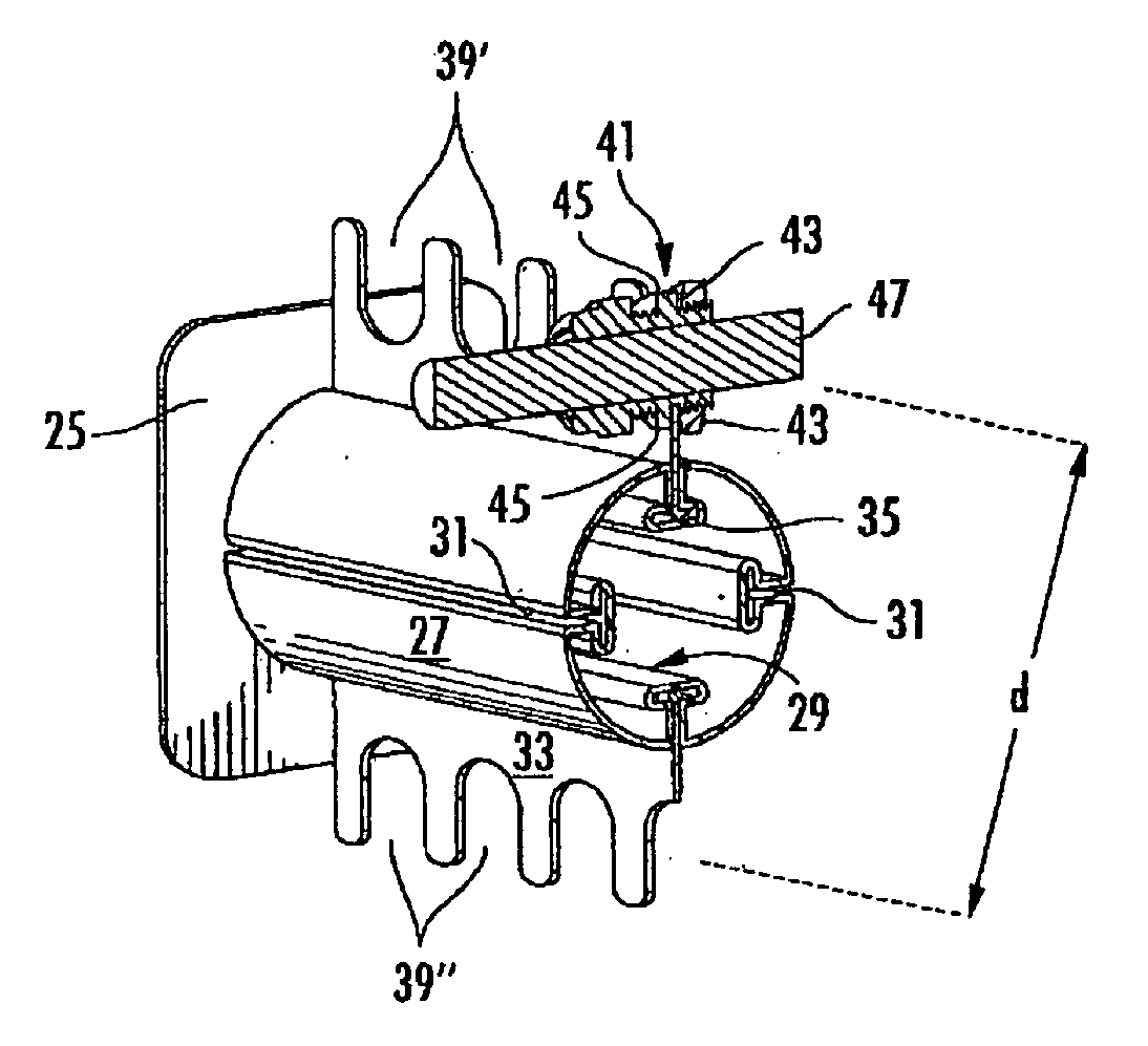
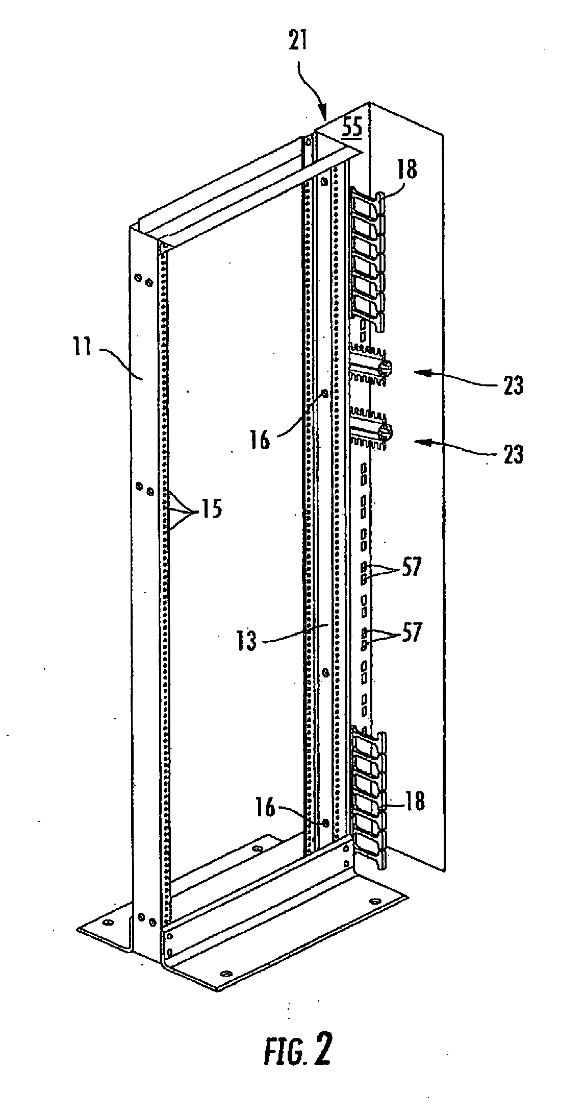
[0017]This and other objects are accomplished by a cable gland holder including a base member and a core for holding a plurality of cable glands. In one embodiment, a plate is removably attached to the core. In another embodiment, more than one plate is attached

Problems solved by technology

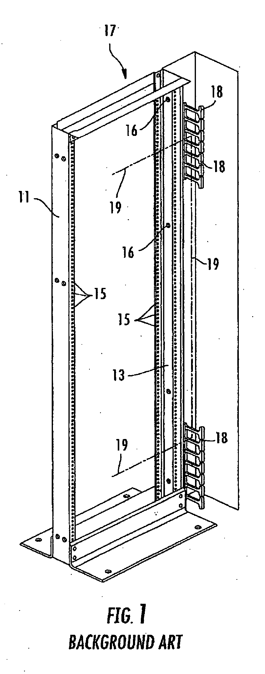
When fiber optic cables are used in conjunction with the devices of the background art, there is a risk of exceeding the minimum bend radius of the fiber optic cable at the point where the fiber optic cable transitions from the horizontal direction to the vertical direction inside the raceway.
Applicants have also appreciated that the pulling force exerted on existing cables within the raceway as a new cable is installed may lead to momentary disconnections of existing communications channels.
If the momentary displacement of the ferrule is sufficient (e.g., more than half a wave length)

Method used


Image

  • Cable spool for use with glanded fiber trucks
  • Cable spool for use with glanded fiber trucks
  • Cable spool for use with glanded fiber trucks

Examples


Embodiment Construction

[0029]The present invention now is described more fully hereinafter with reference to the accompanying drawings, in which embodiments of the invention are shown. This invention may, however, be embodied in many different forms and should not be construed as limited to the embodiments set forth herein; rather, these embodiments are provided so that this disclosure will be thorough and complete, and will fully convey the scope of the invention to those skilled in the art.

[0030]Like numbers refer to like elements throughout. In the figures, the thickness of certain lines, layers, components, elements or features may be exaggerated for clarity. Broken lines illustrate optional features or operations unless specified otherwise.

[0031]The terminology used herein is for the purpose of describing particular embodiments only and is not intended to be limiting of the invention. Unless otherwise defined, all terms (including technical and scientific terms) used herein have the same meaning as c...


PUM


Abstract

A cable gland holder includes a base member and a core for holding a plurality of cable glands. In one embodiment, a plate is removably attached to the core. In another embodiment, more than one plate is attached to the core. Each plate has a grooved edge presenting a series of grooves to which cable glands may be attached. The holder may be attached to a vertical or horizontal raceway of a network rack to assist in protecting and organizing the cables within the raceway.

Description

BACKGROUND OF THE INVENTION[0001]1. Field of the Invention[0002]The present invention relates to a management apparatus for cables. More particularly, the present invention relates to a device for holding a plurality of cables with attached cable glands for purposes of restraint and routing of cables within a network or equipment rack.[0003]2. Description of the Related Art[0004]Cable glands are well known in the existing arts. A cable gland is generally a structure which is mechanically fixed to an outer jacket of a cable, typically by a frictional fit, compression fit or possibly an adhesive. The cable gland also has attachment features which allow the cable gland to be attached to a secondary object, such as a housing, plate, or guide. The cable gland thereby provides strain relief to the cable. In other words, a pulling force applied to the cable's jacket will be transmitted, via the jacket, to the cable gland and hence to the secondary object (e.g., a housing or a guide). There...

Claims


Application Information

Patent Timeline
IPC IPC(8): H02B1/20H02G15/007
CPCH04Q1/062H04Q1/064
Inventor WOMACK, WADELIVINGSTON, JOSEPH C.
Owner COMMSCOPE INC
Why Eureka
Try Eureka