Illumination device for display device, display device, and television receiver

a technology of display device and display device, which is applied in the direction of illuminated signs, display means, instruments, etc., can solve the problems of limited displacement direction of sheet members, and achieve the effect of avoiding deterioration of displaying quality

Inactive Publication Date: 2009-03-05
SHARP KK
View PDF13 Cites 28 Cited by
  • Summary
  • Abstract
  • Description
  • Claims
  • Application Information

AI Technical Summary

Benefits of technology

[0011]In order to overcome the problems described above, preferred embodiments of the present invention prevent wrinkles from being formed on an optical sheet (sheet member) that is to be provided in a display device, while avoiding deterioration of a displaying quality.
[0013]In the configuration, the direction in which the sheet member is displaced due to bending of the optical sheet is limited to the direction towards the inside, even if the sheet member expands or contracts. Thus, cyclic deformation (wavelike wrinkle) on the sheet member is prevented.
[0014]Further, in the configuration, the displacement direction of the sheet member is limited to the direction towards the inside the illumination device. Therefore, the sheet member does not contact the display panel. Thus, it is possible to prevent deterioration of the displaying quality which is attributed to the sheet member contacting the display panel. As a result, with the configuration, it possible to prevent the sheet member from being wrinkled while avoiding deterioration of the displaying quality.
[0016]With the configuration, the direction in which the sheet member is displaced due to bending of the optical sheet is limited to the direction towards the inside, even if the sheet member expands or contracts. Thus, cyclic deformation (wavelike wrinkle) on the sheet member is prevented.
[0017]Further, in the configuration, the displacement direction of the sheet member is limited to the direction towards the inside the illumination device. Therefore, the sheet member does not contact the display panel. Thus, it is possible to prevent deterioration of the displaying quality which is attributed to the sheet member contacting the display panel. In short, with the configuration, it is possible to prevent the sheet member from being wrinkled while avoiding deterioration of the displaying quality.
[0018]A television receiver according to another preferred embodiment of the present invention includes any of the above-described display devices. Thus, it is possible to prevent the sheet member from being wrinkled while avoiding deterioration of the displaying quality.

Problems solved by technology

Further, in the configuration, the displacement direction of the sheet member is limited to the direction towards the inside the illumination device.

Method used


Image

  • Illumination device for display device, display device, and television receiver
  • Illumination device for display device, display device, and television receiver
  • Illumination device for display device, display device, and television receiver

Examples


Embodiment Construction

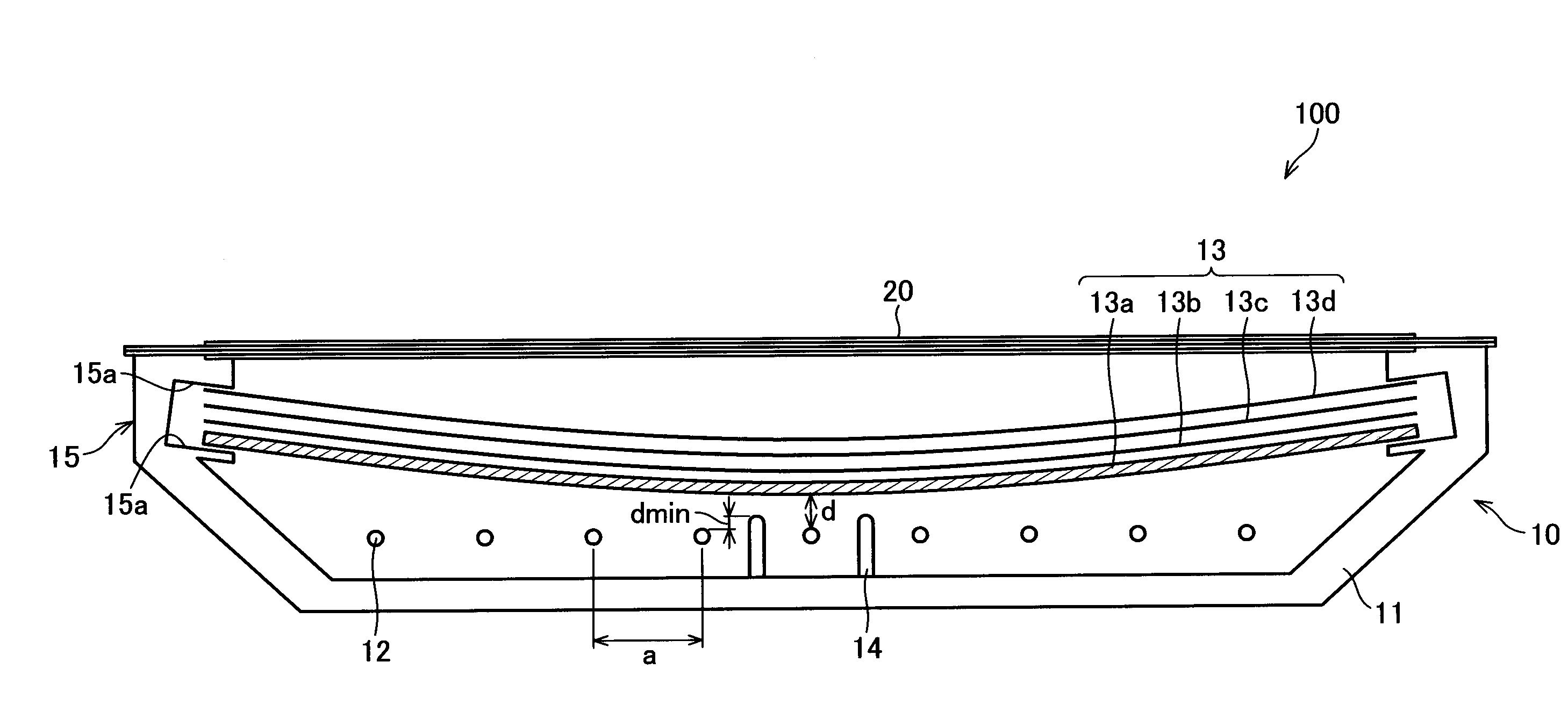
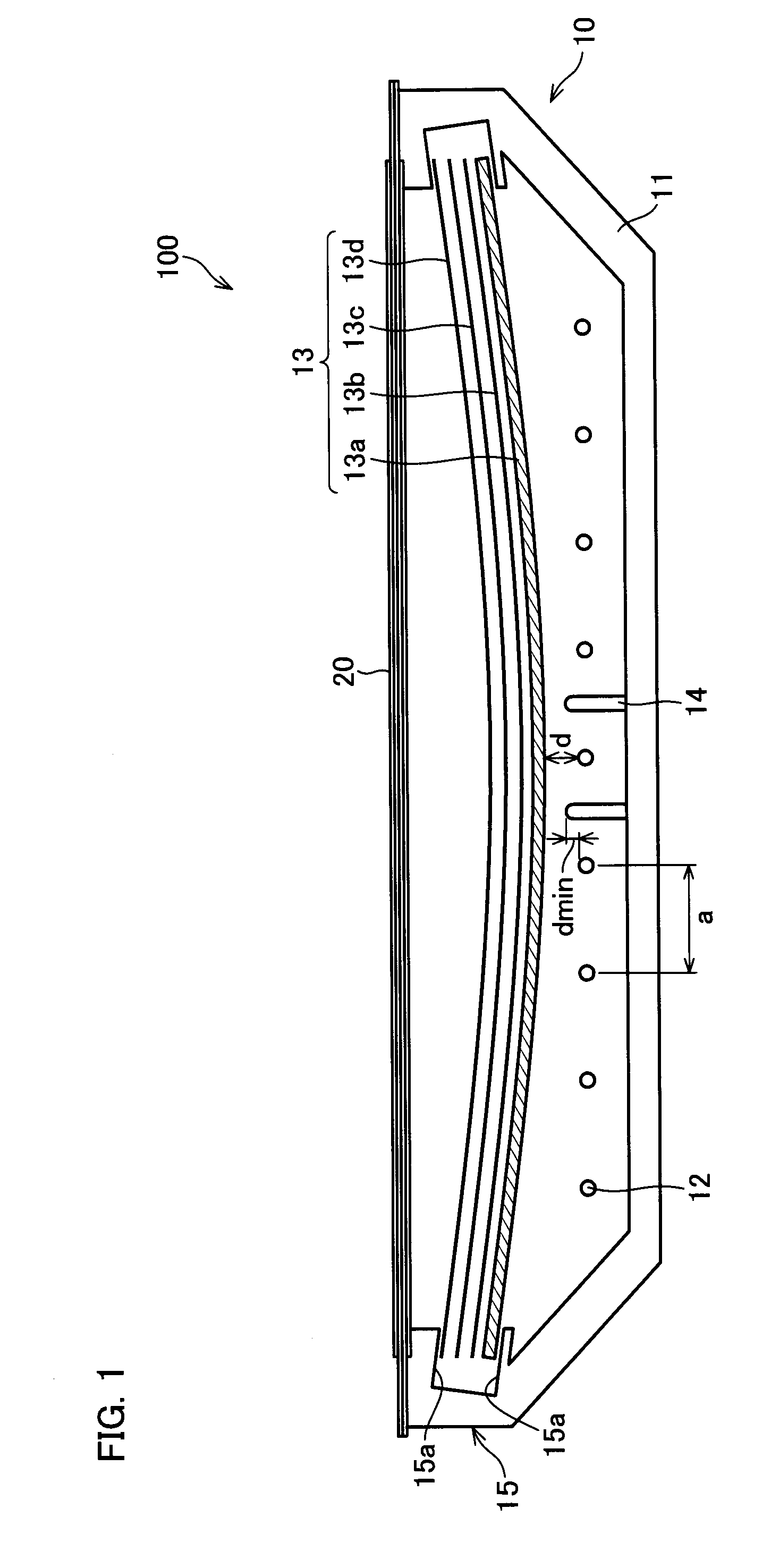
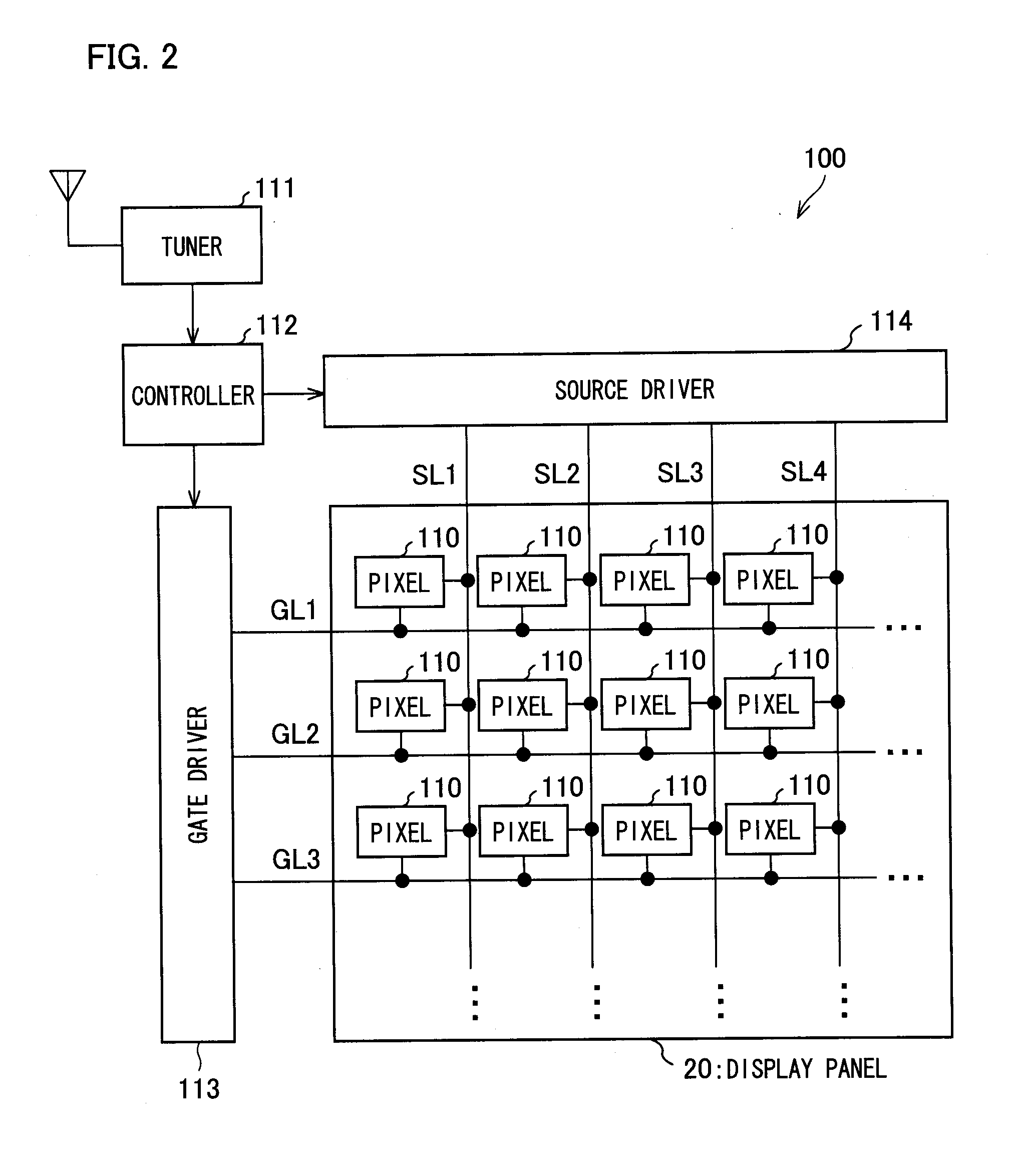
[0030]The following describes preferred embodiments of the present invention. FIG. 1 is a cross sectional view showing a schematic configuration of a display device (television receiver) 100 of the present preferred embodiment. Further, FIG. 2 is a block diagram showing a circuit configuration of the display device 100.

[0031]As shown in FIG. 1, the display device 100 preferably includes: a liquid crystal panel (display panel) 20; and a backlight unit 10.

[0032]First described below are the configuration of the liquid crystal panel 20 and how the display device 100 performs displaying. As shown in FIG. 2, the display device 100 preferably includes: the liquid crystal panel 20 in which pixels 110 are arranged in a matrix manner; a tuner 111; a controller 112; a gate driver 113; a source driver 114; or the like.

[0033]The tuner (image receiving means) 111 receives television broadcasting, generates an image signal according to an image transmitted by the television broadcasting, and tran...


PUM


Abstract

In a display device having a liquid crystal panel and a backlight unit, an optical sheet group provided on a surface of the backlight unit facing the liquid crystal panel is curved so as to form a convex shape in a direction opposite to the liquid crystal panel. In this way, a wrinkle on the optical sheet provided in the display device is prevented while avoiding deterioration in the displaying quality.

Description

BACKGROUND OF THE INVENTION[0001]1. Field of the Invention[0002]The present invention relates to a backlight unit (illumination device) for use in a transmissive display device, a display device, and a television receiver. More specifically, the present invention relates to a technology for preventing a wrinkle which cyclically occurs on an optical sheet (sheet member) provided to the transmissive display device, while avoiding deterioration in the displaying quality.[0003]2. Description of the Related Art[0004]In recent years, flat panel displays such as liquid crystal display devices have been widely spreading as monitors for television receivers and PCs (personal computers). Particularly, in the field of television receivers, there has been a demand for larger display screens.[0005]A liquid crystal display device is a representative example of non-light emitting display devices. A liquid crystal display device can be, for example: a transmissive liquid crystal display device whic...

Claims


Application Information

Patent Timeline
Patent Type & Authority Applications(United States)
IPC IPC(8): G09F13/08
CPCG02F2201/54G02F1/133606
Inventor TAKATA, YOSHIKIYOKOTA, MASASHI
Owner SHARP KK
Why Eureka
Try Eureka