
Robotic tire spraying system

a tire spraying and tire technology, applied in the direction of superimposed coating process, liquid/solution decomposition chemical coating, manufacturing tools, etc., can solve the problems of time-consuming and labor-intensive manual application of coatings by spraying or brushing, and achieve the effect of optimal spray coverag

Active Publication Date: 2009-03-05
PIONEER IND SYST
View PDF9 Cites 25 Cited by
  • Summary
  • Abstract
  • Description
  • Claims
  • Application Information

AI Technical Summary

Benefits of technology

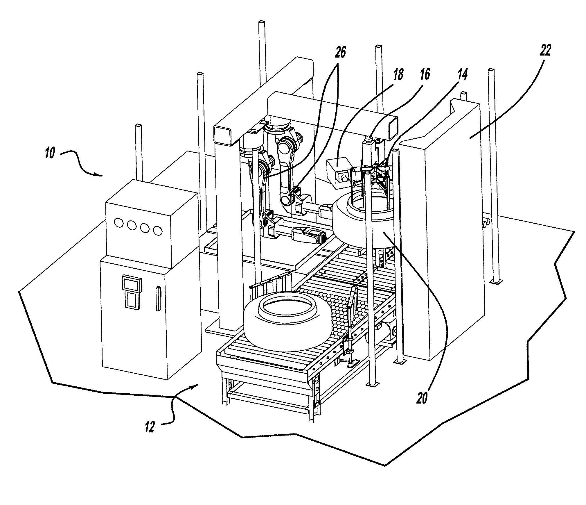
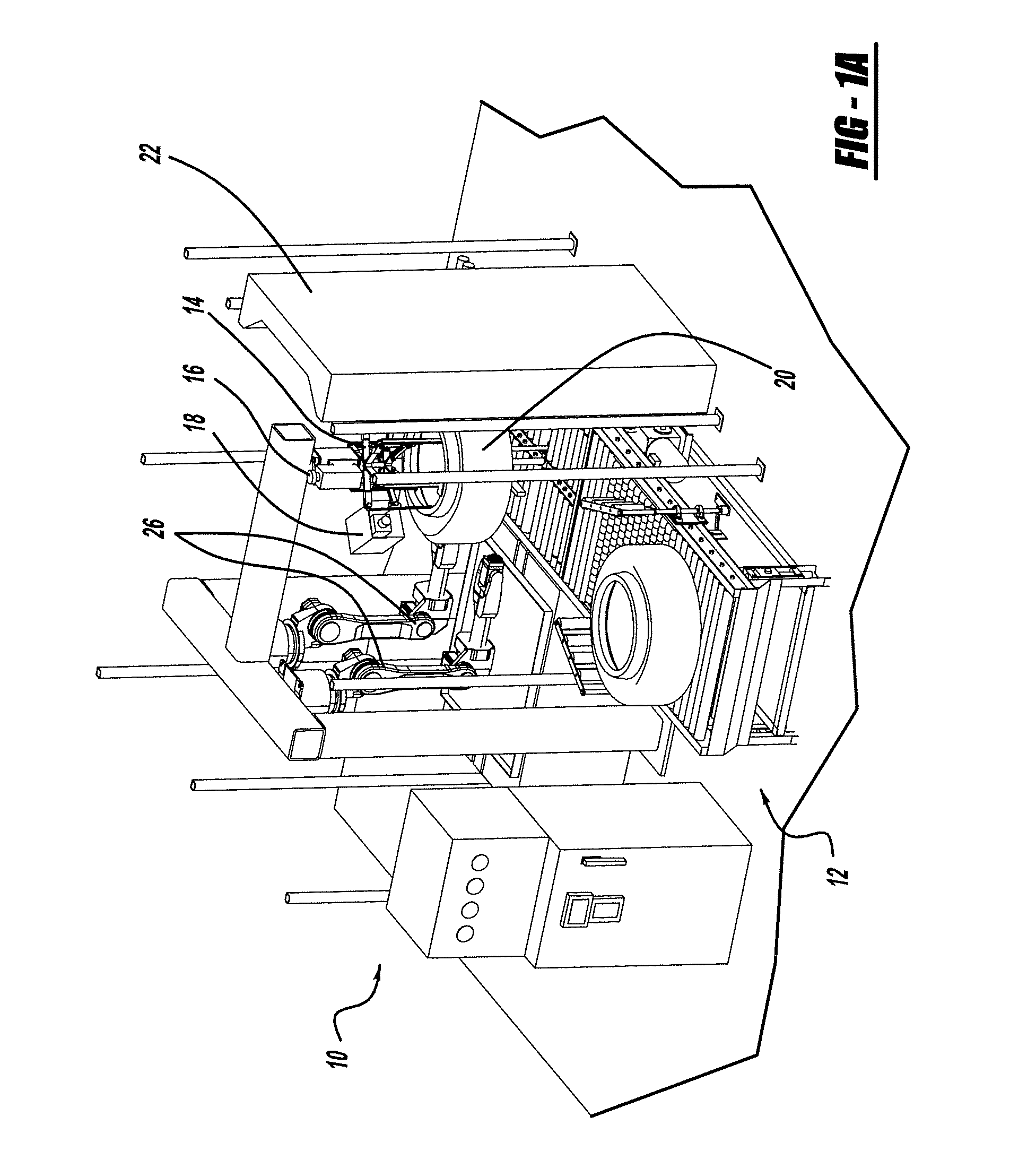
[0013]According to the present invention, a robotic spray system is provided for accurately spraying mold release onto any size or shaped green tire. The system analyzes individual green tires using an integrated vision system. The system controls the robotic spray position, the fan, fluid, atomizing air, and tire rotation speed for optimal spray coverage on both the inside and outside of green tires.
[0016]The advantages of the tire spraying system of the present invention include fully programmable spray and spray positioning for fluid, fan and atomizing, maximizing the efficiency of spray material used and the positioning of the spray. By having a precise spray, overspray is drastically reduced, resulting in a reduction in material costs.
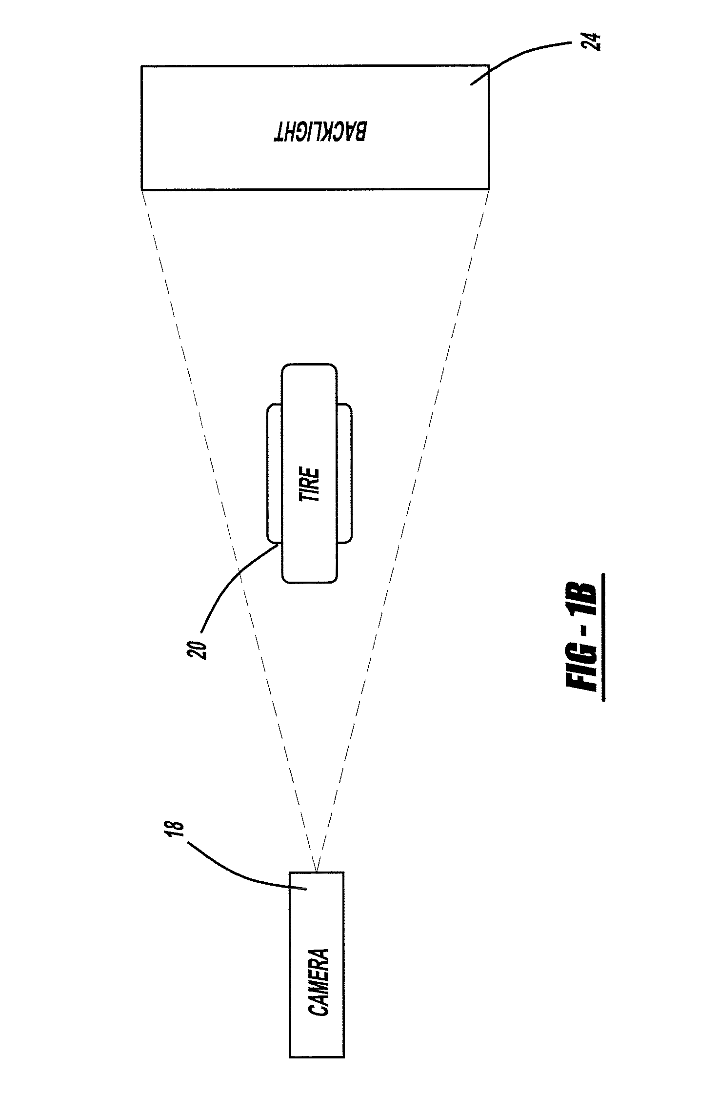
[0017]Using vision cameras to dynamically adjust robot spray positions based on varying tire profiles provides the ultimate flexibility to run different tire sizes.
[0018]Implementing modern technology with traditional conveying and chucking allows retro-fitting of existing systems with the present invention. Implementing the novel system in an existing or newly constructed system, such as a dual conveyor system, will produce a coated green tire approximately every 7-9 seconds while accurately placing the proper amount of inside and outside tire lube in only the areas specified with minimal overspray. A single conveyor system will deliver a coated green tire approximately every 12-14 seconds.
[0022]The robot is the main motion element of the system. Robots are highly reliable and repeatable. The system does not index heavy tires on swing arms using traditional mechanical indexers.

Problems solved by technology

Also, applying the coatings manually by either spraying or brushing is time consuming and laborious.

Method used


Image

  • Robotic tire spraying system
  • Robotic tire spraying system
  • Robotic tire spraying system

Examples


Embodiment Construction

[0032]The following detailed description and appended drawings describe and illustrate various exemplary embodiments of the invention. The description and drawings serve to enable one skilled in the art to make and use the invention, and are not intended to limit the scope of the invention in any manner. In respect of the methods disclosed, the steps presented are exemplary in nature, and thus, the order of the steps is not necessary or critical.

[0033]A traditional tire sprayer employs high pressure, high volume guns resulting in overspray, requires a large footprint and has a cycle time of approximately 7-10 sec. These sprayers require large exhaust fans and a different model sprayer for different tire ranges. Further, these sprayers do not typically include a bar code mask, or pressure or flow sensing.

[0034]The present invention advantageously combines robotics with a vision system, eliminating the disadvantages of traditional tire sprayers. The robots are preferably provided with...


PUM

PropertyMeasurementUnit
processing timeaaaaaaaaaa
timeaaaaaaaaaa
timeaaaaaaaaaa

Abstract

A robotic spray system is provided for accurately spraying mold release onto any size or shaped green tire. The system analyzes individual green tires using an integrated vision system. The system controls the robotic spray position, the fan, fluid, atomizing air, and tire rotation speed for optimal spray coverage on both the inside and outside of green tires. The system includes a conveyor, an overhead mounted camera located over an infeed station, and a second camera located perpendicular to the green tire's tread and several feet away from the center of the tire. Pictures of the green tire in the station are used to estimate the center and radius of the tire and locate the angle of the bar code with respect to the center of the tire. Reference points are provided from the camera images and robot positions are calculated to control the spraying.

Description

FIELD OF THE INVENTION[0001]This invention relates to a method of and an apparatus for coating green or uncured tires. More particularly, the invention is directed to a system for robotically spraying a coating on predetermined areas both inside and outside green tires.BACKGROUND OF THE INVENTION[0002]Conventionally, pneumatic rubber tires are produced by molding and curing a green, or uncured, tire in a molding press in which the green tire is pressed outwardly against a mold surface by means of an inner fluid expandable bladder. By this method, the green tire is shaped against the outer mold surface which typically defines the tire's tread pattern and configuration of sidewalls. By application of heat, the tire is cured. Generally, the bladder is expanded by internal pressure provided by a fluid such as hot gas, hot water and / or steam which also participates in the transfer of heat for curing or vulcanization purposes. The tire is then usually allowed to cool somewhat in the mold,...

Claims


Application Information

Patent Timeline
Patent Type & Authority Applications(United States)
IPC IPC(8): B05D1/02B05C7/02
CPCB05B12/12B05B12/122B05D1/002B29D30/0662B05D2201/02B29C37/0067B05D1/02B05B12/126
Inventor HENDRICKS, SR., TODD E.
Owner PIONEER IND SYST
Learn More