Multi-response time burner system for controlling combustion driven pulsation

a technology of combustion driven pulsation and burner system, which is applied in the direction of machines/engines, mechanical equipment, lighting and heating apparatus, etc., can solve the problems of time lag between the heat release peak arriving at the combustion chamber and so as to reduce the potential for generating unacceptable acoustic pulsations

Inactive Publication Date: 2009-03-05
GAS TECH INST
View PDF11 Cites 22 Cited by
  • Summary
  • Abstract
  • Description
  • Claims
  • Application Information

AI Technical Summary

Benefits of technology

[0011]In accordance with the method of this invention, a burner nozzle is positioned in each of a plurality of burner nozzle openings formed by at least one wall of a combustion chamber with at least a portion of the burner nozzles having internal dimensions different from others of the burner nozzles. A fuel and oxidant are premixed by introduction into each of the burner nozzles, resulting in a fuel / oxidant mixture within the burner nozzles. The fuel / oxidant mixtures are ignited, resulting in combustion of the fuel / oxidant mixtures and producing a plurality of heat release patterns with phase shift within the combustion chamber. Phase shift refers to the relative axial locations of the heat release pulsations within the combustion chamber. Thus, while one of the burner nozzles may produce a heat release pulsation which matches one of the natural frequencies of the combustion chamber, the other nozzles will have heat release pulsations which most probably do not match the natural frequencies of the combustion chamber, thereby reducing the potential for generation of unacceptable acoustic pulsations.

Problems solved by technology

As a result, the burner nozzles having larger internal dimensions respond to a pressure disturbance within the combustion chamber affecting the fuel / oxidant ratio slower than the burner nozzles having smaller internal dimensions, resulting in time lags between the heat release peaks arriving at the combustion chamber.
Thus, while one of the burner nozzles may produce a heat release pulsation which matches one of the natural frequencies of the combustion chamber, the other nozzles will have heat release pulsations which most probably do not match the natural frequencies of the combustion chamber, thereby reducing the potential for generation of unacceptable acoustic pulsations.

Method used


Image

  • Multi-response time burner system for controlling combustion driven pulsation
  • Multi-response time burner system for controlling combustion driven pulsation
  • Multi-response time burner system for controlling combustion driven pulsation

Examples


Embodiment Construction

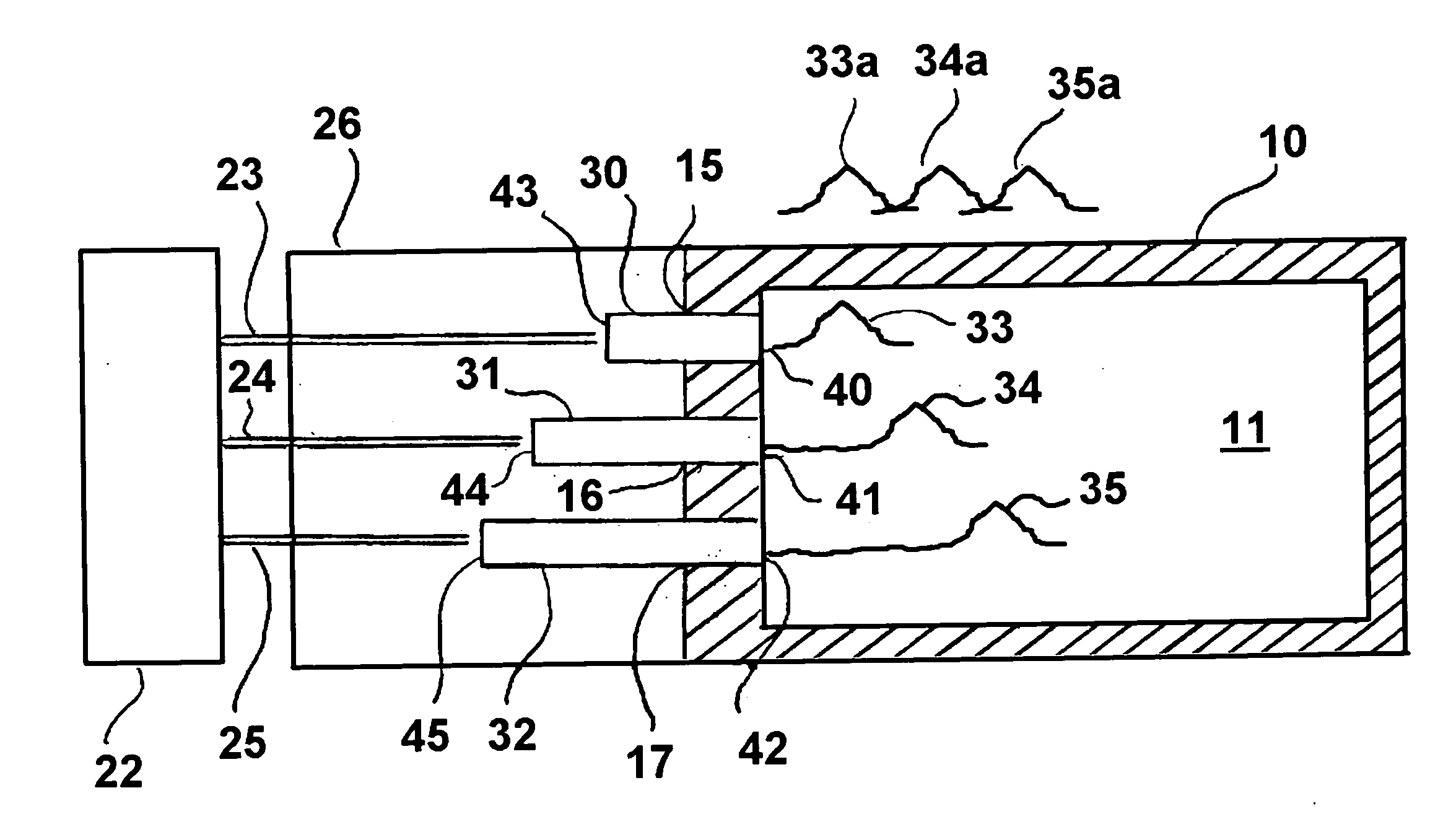
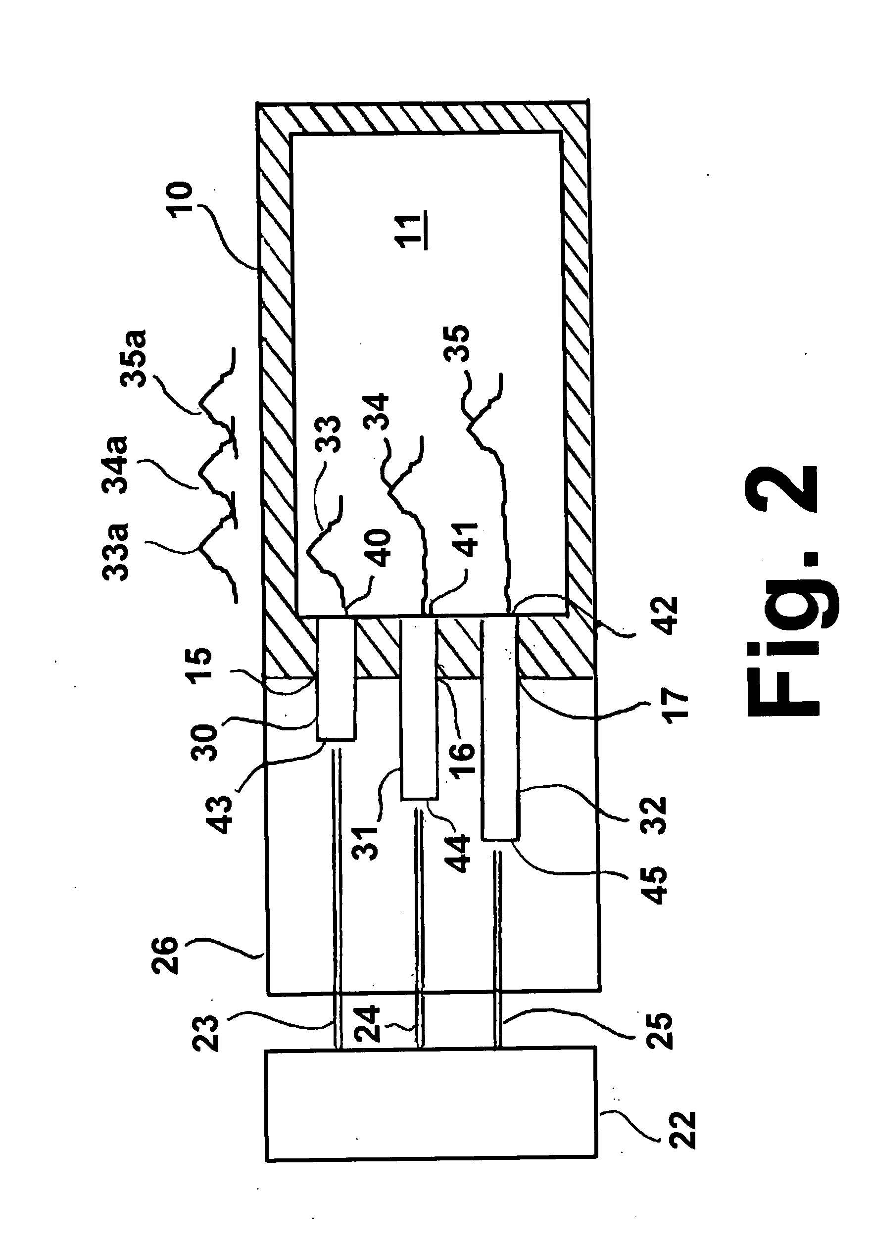
[0016]As used herein, the term “delivery response time” refers to the period of time extending from the occurrence of a pressure disturbance within a combustion chamber to the point in time at which the altered fuel / oxidant mixture, having been altered by the pressure disturbance, is ignited in the combustion chamber. As used herein, the term “disturbance response time” is interchangeable with the delivery response time.

[0017]The disturbance response time T of a burner nozzle is calculated as

T=T1+T2+T3

where T1 is the time for a pressure disturbance in the combustion system to travel at the speed of sound to the nozzle fuel / air inlet to affect the fuel and air flow; T2 is the time for the fuel / air mixture to travel from the nozzle inlet to its outlet, i.e.

T2=Vol / Q

where Vol is the interior volume of the burner nozzle and Q is the volume flow rate through the corresponding burner nozzle. T3 is the time period from the fuel / air mixture exiting from the nozzle tip to the onset of the f...


PUM


Abstract

A combustion system having at least one wall enclosing a combustion chamber and forming a plurality of burner or burner nozzle openings. Disposed within each of the openings is a premix burner or burner nozzle, each of which has a premixed fuel/oxidant outlet proximate the combustion chamber and a fuel/oxidant inlet distal from the combustion chamber. At least a portion of the premix burners or burner nozzles are sized to produce different fuel/oxidant delivery disturbance response times in response to a pressure disturbance within the combustion system. Differences in fuel/oxidant delivery response times are achieved by using burners or burner nozzles having different internal dimensions, different volume flow rates, and, optionally, by varying the fuel/oxidant ratios of the mixtures flowing through the burners or burner nozzles.

Description

BACKGROUND OF THE INVENTION[0001]1. Field of the Invention[0002]This invention relates to a combustion system and method for reducing or eliminating combustion driven acoustic pulsations that occur in industrial combustion systems employing premix or partial premix industrial burners. More particularly, this invention relates to premix or partial premix burners or burner systems for use in boilers, process heaters and the like which reduce or eliminate combustion driven acoustic pulsations normally generated by conventional premix or partial premix burners or burner systems.[0003]2. Description of Related Art[0004]Conventional premix or partial premix burners utilized, for example, in boilers, are inherently subject to combustion instability in the combustion chamber as represented by dynamic pressure oscillations in the combustion chamber. These pressure oscillations, which may occur at various fundamental or predominant resonant frequencies and other higher order harmonic, are cap...

Claims


Application Information

Patent Timeline
Patent Type & Authority Applications(United States)
IPC IPC(8): F23M13/00F02C7/24F23R3/28F23M20/00
CPCF23M20/005F23R2900/00014
Inventor WANG, DEXINCYGAN, DAVID F.KNIGHT, RICHARD A.
Owner GAS TECH INST
Why Eureka
Try Eureka