Connector, jack socket component, electronic equipment and plug component
- Summary
- Abstract
- Description
- Claims
- Application Information
AI Technical Summary
Benefits of technology
Problems solved by technology
Method used
Image

Examples
first embodiment
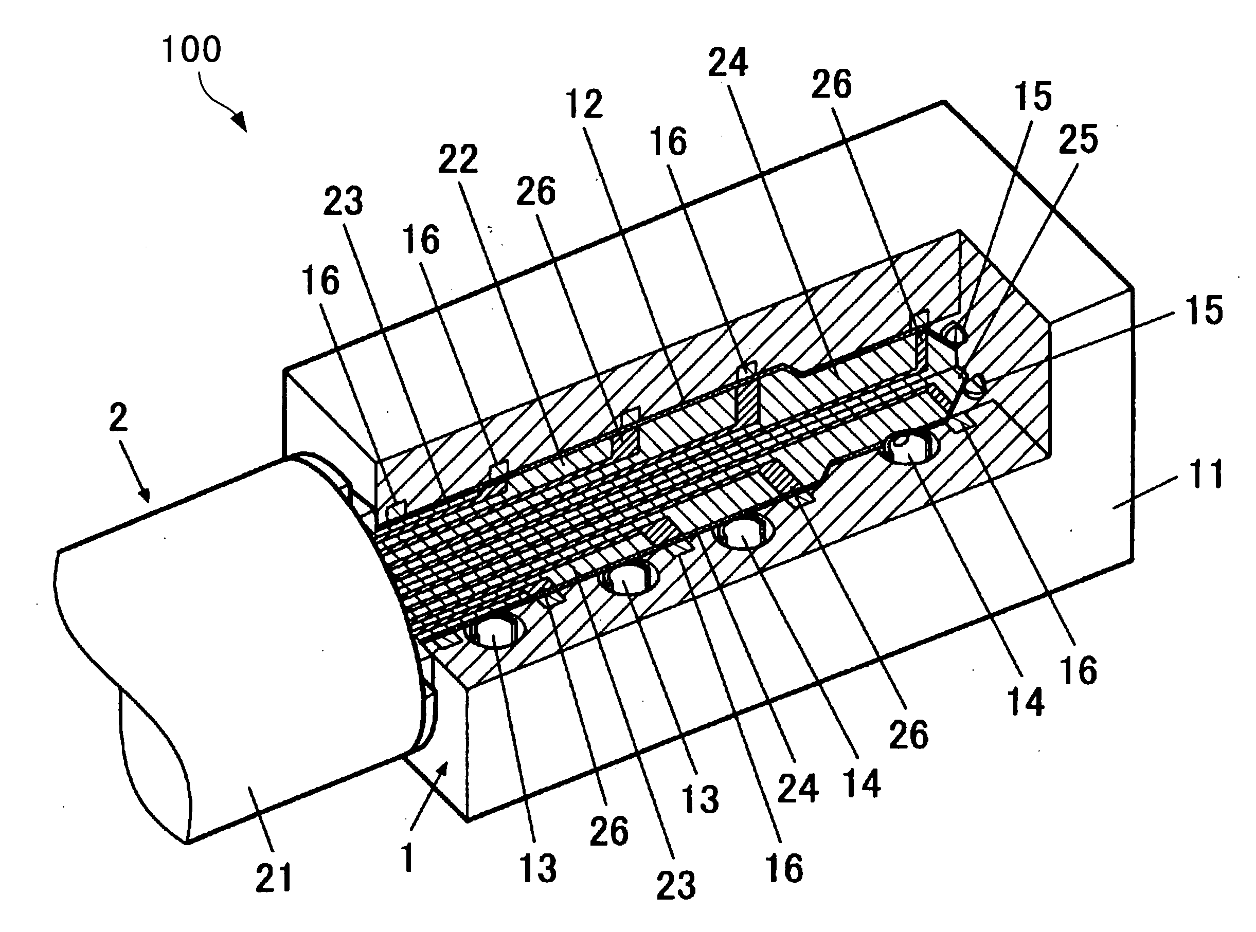
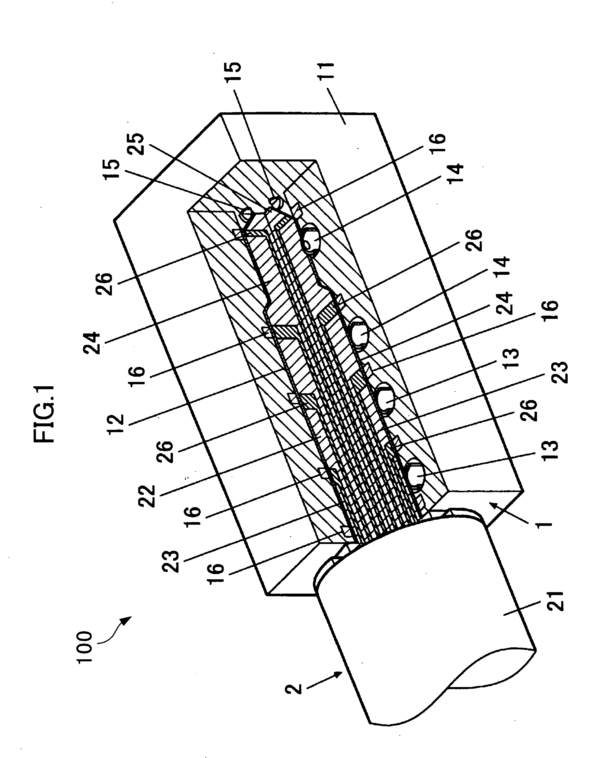
[0030]A configuration for a first embodiment of a waterproof connector structure to which the present invention is applied is shown in FIG. 1. FIG. 1 is a perspective internal view cut-away at right-angles of a situation where a plug is fitted in a jack socket.
[0031]A connector 100 includes a jack socket 1 and a plug 2.
[0032]The jack socket 1 includes an insulator 11, an insertion hole 12, power supply terminals 13, signal terminals 14, fitting detection terminals 15, and elastic seal members 16. The jack socket 1 includes the insertion hole 12 that opens up at a surface of the insulator 11, as shown in the drawings. A number of power supply terminals 13 and a number of signal terminals 14 are provided respectively at predetermined intervals in a depth direction from the opening at a cylindrical inner wall of the insertion hole 12. Specifically, a pair of the power supply terminals 13 are provided from the side of the opening of the insertion hole 12, and a pair of the signal termin...
second embodiment
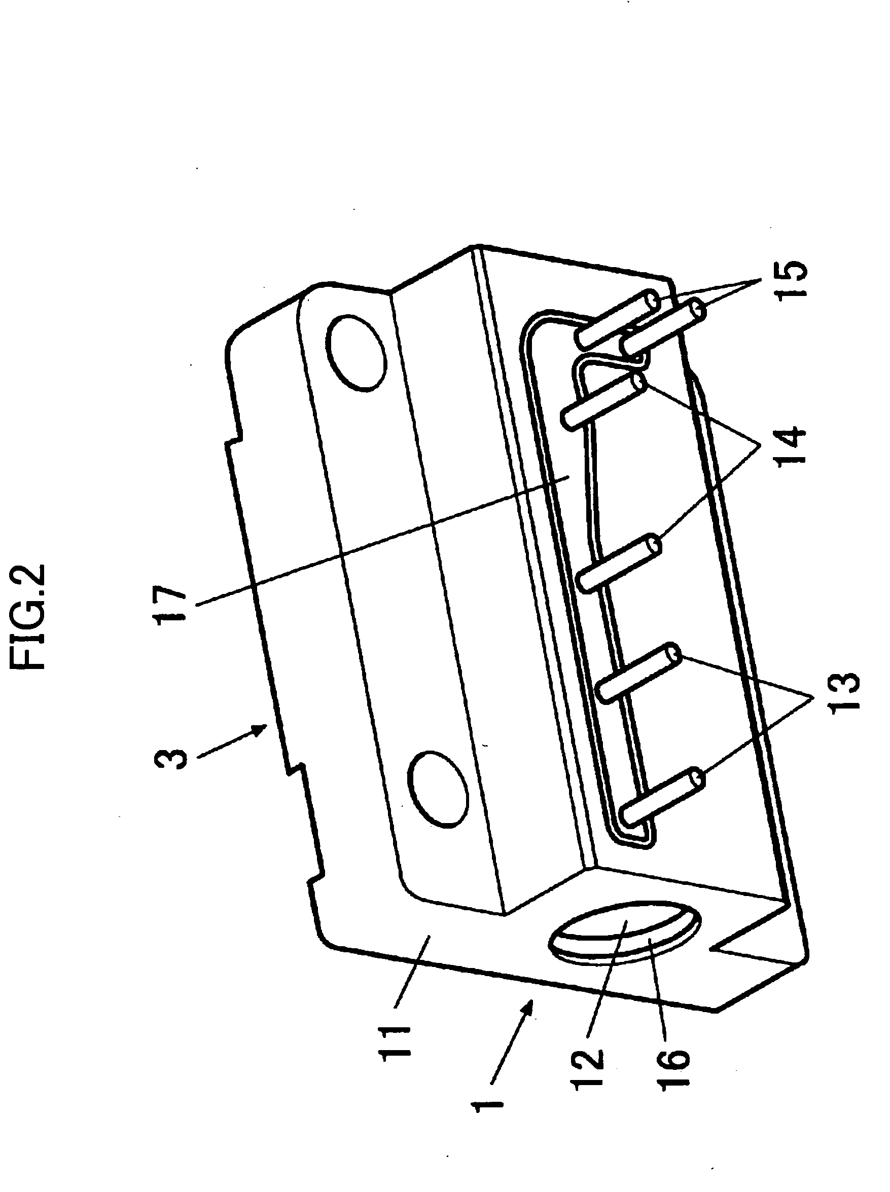
[0044]An example of a structure where the jack socket 1 of FIG. 1 is incorporated into electronic equipment is shown in FIG. 2 to FIG. 9 as a second embodiment.
[0045]FIG. 2 is a view of a jack component 3 including the jack socket 1 of FIG. 1 as viewed from the side for fitting to the casing. FIG. 3 is a longitudinal cross-sectional view showing contacts of the jack component 3 and the seal structure section. The power supply terminals 13, the signal terminals 14 and the fitting detection terminals 15 are lead out to outside of the insulator 11 from the opening provided at the insulator 11. The opening is then sealed by a sealing elastic member 17.
[0046]The power supply terminals 13, the signal terminals 14, and the fitting detection terminals 15 are connected by a connector of a circuit board (not shown). This connecting can take place directly or can take place via a flexible substrate etc.
[0047]FIG. 4 is a view showing electronic equipment 4 where the jack component 3 is incorpor...
first modified example
[0052]An example configuration of a type where fastening of the seal member is improved using a wedge-shaped member is shown as a first modified example. FIG. 10A shows the situation just before insertion of the plug 2 into the jack socket 1. FIG. 10B shows the situation of insertion and fitting of the plug 2 into the jack socket 1.
[0053]In the first modified example, in order to alleviate resistance to insertion of the plug 2 while ensuring waterproofing performance, at the time of insertion, seal tightness of an elastic seal member 16a on the insertion opening side of the insertion hole 12 is improved. As shown in the drawing, a ring-shaped recess 18 is formed at the periphery of the open end of the insertion hole 12 of the insulator 11. The elastic seal member 16a is then disposed at this ring-shaped recess 18. On the other hand, a ring-shaped wedge section 28 is provided at the periphery of the base of the pin 22 of the plug 2.
[0054]The elastic seal member 16a is then supported ...
PUM
 Abstract
Description
Claims
Application Information
 - Generate Ideas
- Intellectual Property
- Life Sciences
- Materials
- Tech Scout
- Unparalleled Data Quality
- Higher Quality Content
- 60% Fewer Hallucinations
Browse by: Latest US Patents, China's latest patents, Technical Efficacy Thesaurus, Application Domain, Technology Topic, Popular Technical Reports.
© 2025 PatSnap. All rights reserved.Legal|Privacy policy|Modern Slavery Act Transparency Statement|Sitemap|About US| Contact US: help@patsnap.com