Process for separating a heavy oil feedstream into improved products
a technology of heavy oil and feedstream, applied in the direction of organic chemistry, membranes, thermal non-catalytic cracking, etc., can solve the problems of high operating cost and significant loss of valuable components in the final produ
- Summary
- Abstract
- Description
- Claims
- Application Information
AI Technical Summary
Problems solved by technology
Method used
Image
Examples
example 1
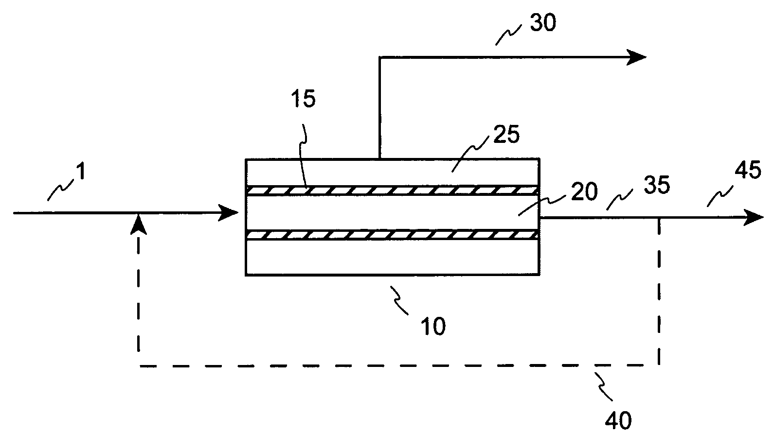
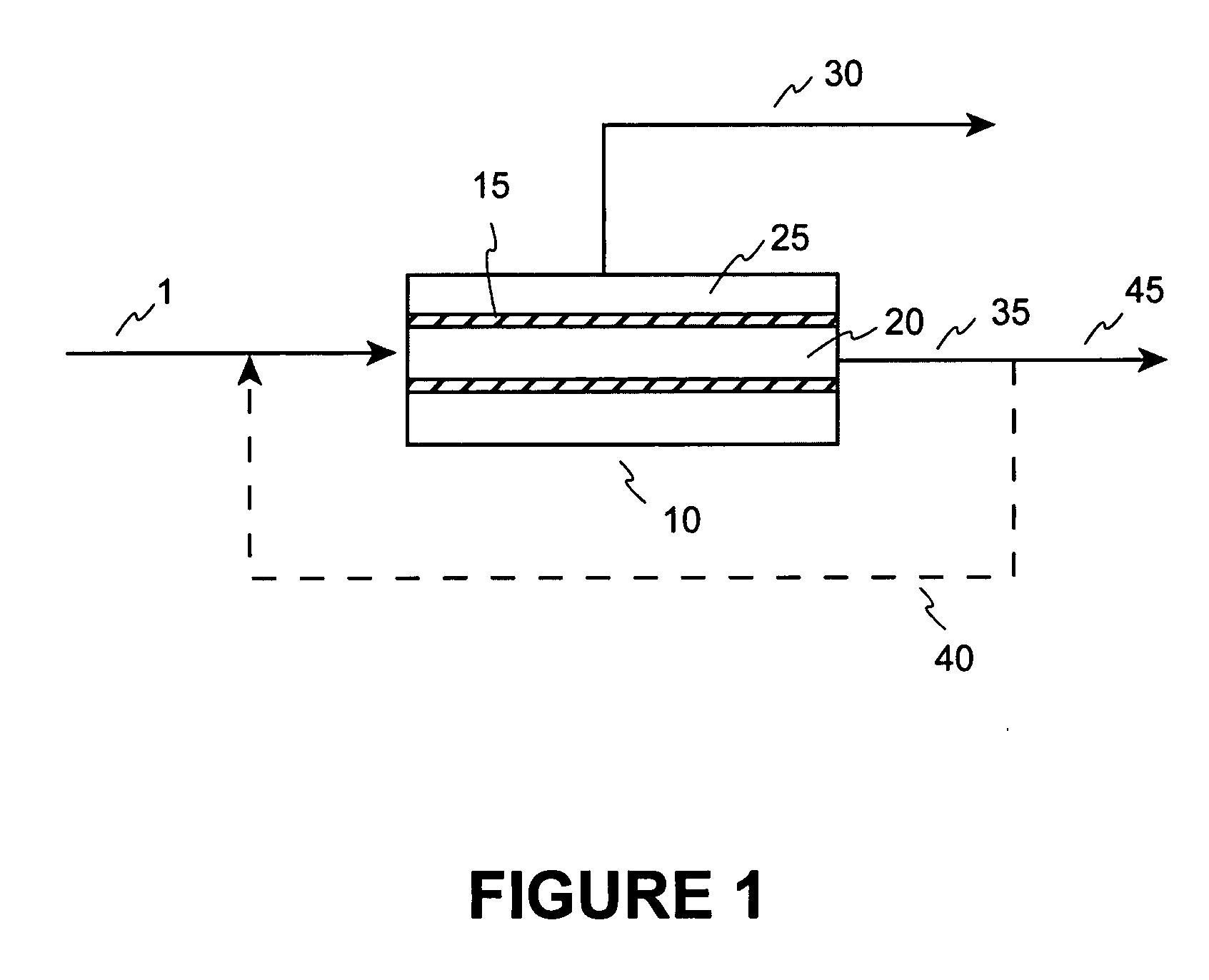
[0069]In this Example, the transmembrane pressure control setpoint was 400 psi (similar to Examples 2, 3, and 4). The combined feedstream temperature setpoint was 260° C. (similar to Examples 2 and 4). The fresh feed pump steady state flow rate was approximately 5.74 grams / min and the recycle pump steady state flow rate setpoint was approximately 15,235 grams / min. The ratio of the recycle flow rate to the fresh feed flow rate was approximately 2,654. This created a calculated crossflow velocity through the membrane modules of about 3.2 ft / s (0.98 m / s). The pilot plant unit was lined out to achieve a steady state operation to generate 50% permeate yield based on the fresh feed rate. After achieving steady state operation, a pair of permeate and retentate samples were collected for 17 hours and 50 minutes and analyzed.
[0070]The process conditions, flux rates, and selectivity results from this Example are shown as Example 1 in Table 1. The analytical test results from this Example are ...
example 2
[0071]In this Example, the transmembrane pressure control setpoint was 400 psi (similar to Examples 1, 3, and 4). The combined feedstream temperature setpoint was 260° C. (similar to Examples 1 and 4). The fresh feed pump steady state flow rate was approximately 15.96 grams / min and the recycle pump steady state flow rate setpoint was approximately 72,097 grams / min. The ratio of the recycle flow rate to the fresh feed flow rate was approximately 4,517. This created a calculated crossflow velocity through the membrane modules of about 15.0 ft / s (4.6 m / s). The pilot plant unit was lined out to achieve a steady state operation to generate 50% permeate yield based on the fresh feed rate. After achieving steady state operation, a pair of permeate and retentate samples were collected for 16 hours and 25 minutes and analyzed.
[0072]The process conditions, flux rates, and selectivity results from this Example are shown as Example 2 in Table 1. The analytical test results from this Example are...
example 3
[0073]In this Example, the transmembrane pressure control setpoint was 400 psi (similar to Examples 1, 2, and 4). The combined feedstream temperature setpoint was raised to 290° C. The fresh feed pump steady state flow rate was approximately 31.44 grams / min and the recycle pump steady state flow rate setpoint was approximately 72,097 grams / min. The ratio of the recycle flow rate to the fresh feed flow rate was approximately 2,293. This created a calculated crossflow velocity through the membrane modules of about 15.0 ft / s (4.6 m / s). The pilot plant unit was lined out to achieve a steady state operation to generate 50% permeate yield based on the fresh feed rate. After achieving steady state operation, a pair of permeate and retentate samples were collected for 6 hours and 47 minutes and analyzed.
[0074]The process conditions, flux rates, and selectivity results from this Example are shown as Example 3 in Table 1. The analytical test results from this Example are shown as Example 3 in...
PUM
| Property | Measurement | Unit |
|---|---|---|
| pore size | aaaaa | aaaaa |
| transmembrane pressure | aaaaa | aaaaa |
| wt % | aaaaa | aaaaa |
Abstract
Description
Claims
Application Information
 - R&D
- Intellectual Property
- Life Sciences
- Materials
- Tech Scout
- Unparalleled Data Quality
- Higher Quality Content
- 60% Fewer Hallucinations
Browse by: Latest US Patents, China's latest patents, Technical Efficacy Thesaurus, Application Domain, Technology Topic, Popular Technical Reports.
© 2025 PatSnap. All rights reserved.Legal|Privacy policy|Modern Slavery Act Transparency Statement|Sitemap|About US| Contact US: help@patsnap.com


