
Sleep diagnosis device

Inactive Publication Date: 2009-03-05
MATSUSHITA ELECTRIC WORKS LTD
View PDF4 Cites 43 Cited by
  • Summary
  • Abstract
  • Description
  • Claims
  • Application Information

AI Technical Summary

Benefits of technology

[0007]In view of the above problem, the object of the present invention is to provide a sleep diagnosis device capable of easing the burden of the patient by reducing the number of sensors and detecting the breathing movement of the patient accurately.
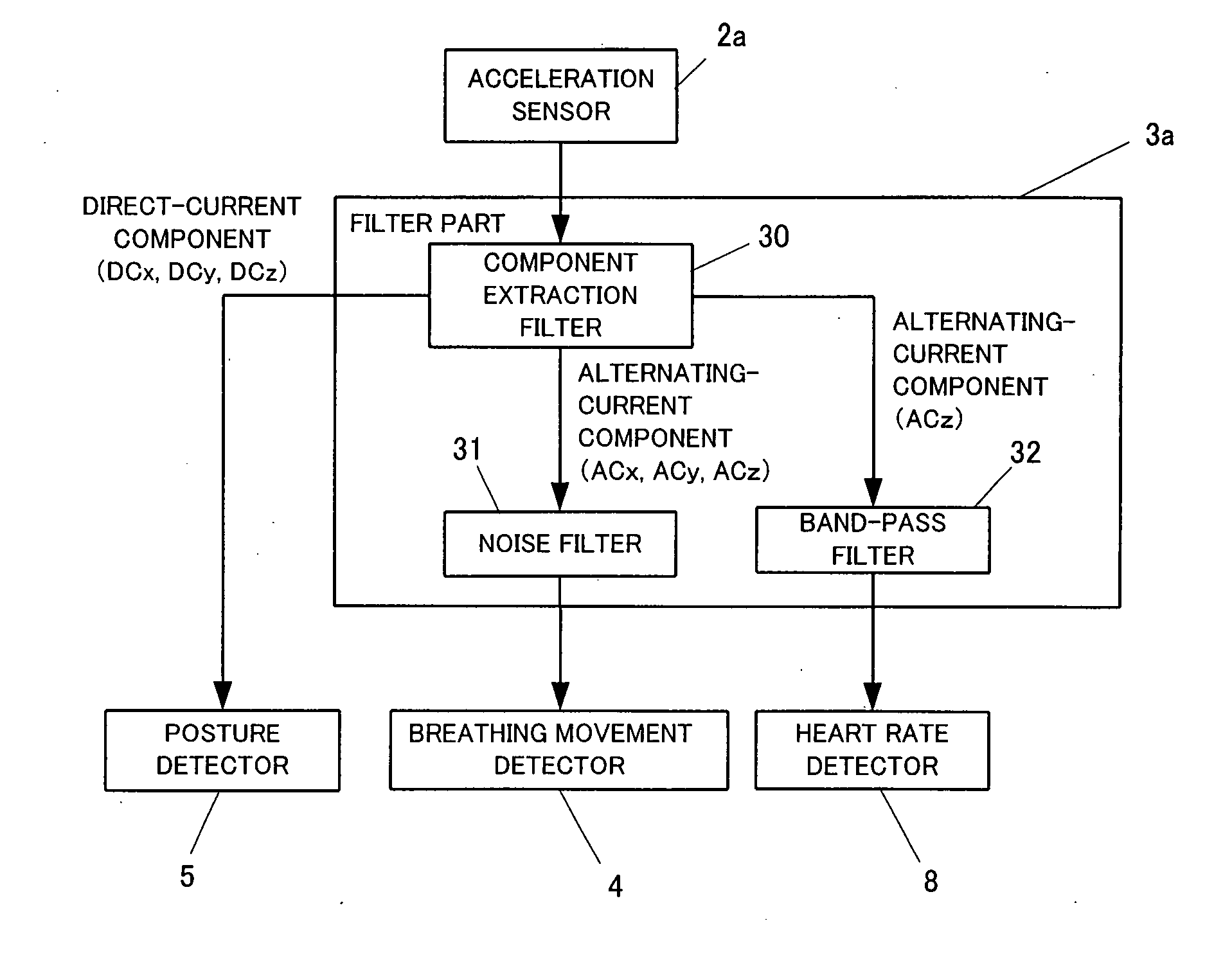
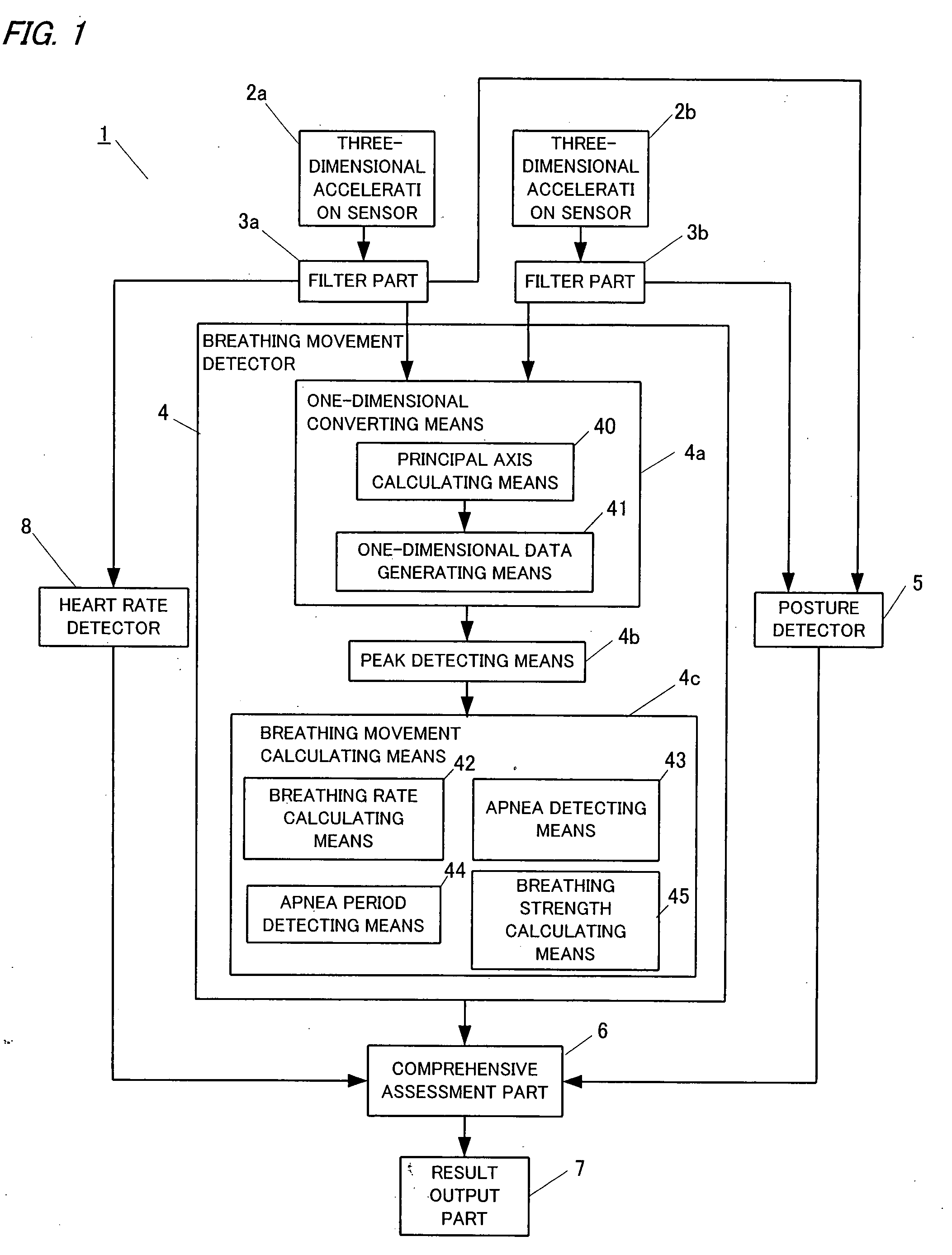
[0009]Because the sleep diagnosis device of the present invention can detect the posture (sleeping posture) and the breathing movement of the patient by using one three-dimensional acceleration sensor, it is not necessary for the sleep diagnosis device of the present invention to separately prepare a body position sensor for detecting a posture of a patient and a respiration sensor for detecting a breathing movement of the patient, whereby it is possible to reduce the number of sensors and ease the burden of the patient. Furthermore, because the sleep diagnosis device of the present invention detects the breathing movement by the three-dimensional acceleration sensor, it is possible to detect the breathing movement accurately in response to the movement of the chest and the belly of the patient in various directions.
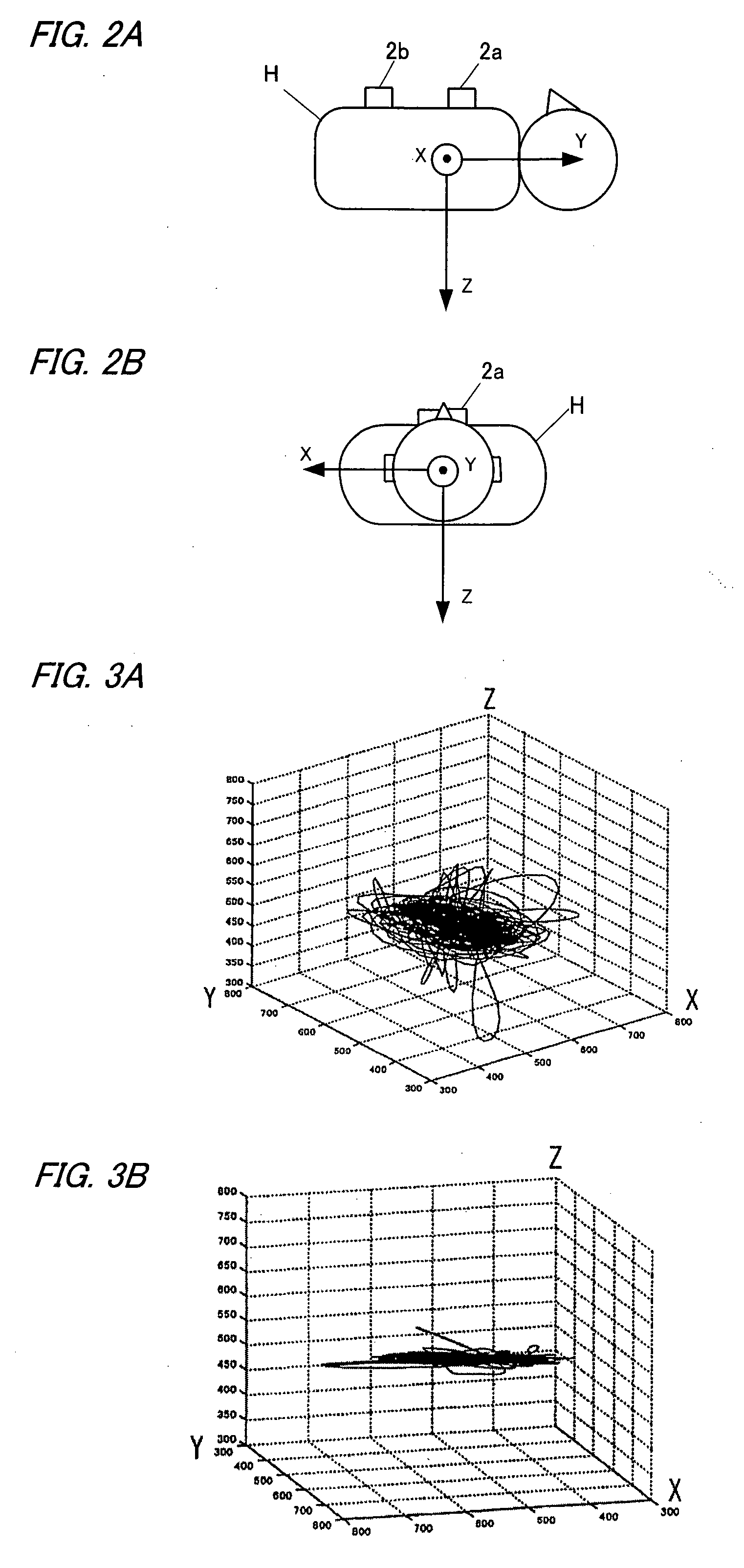
[0013]In this case, it is possible to generate the one-dimensional acceleration data which takes a variation of the principal axis of the acceleration, that is, a principal direction of the movement, into account, and it is possible to obtain the one-dimensional acceleration data in which the variation of the acceleration is accurately reflected.
[0019]In this case, it is possible to detect the apnea interval of the patient accurately.
[0026]In this case, it is possible to detect the heart rate of the patient from the three-dimensional acceleration sensor in addition to the posture and the breathing movement of the patient, whereby it is possible to reduce the number of sensors and to ease the burden of the patient.

Problems solved by technology

Therefore, such a conventional inspection apparatuses is burdensome for a patient to whom various sensors are attached, so it is expected to reduce the number of sensors as much as possible and to ease the burden of the patient.
However, because motions of the chest and the belly by a breathing movement are vary from person to person, an evaluation of the breathing movement based on the acceleration of one direction was inadequate.

Method used


Image

  • Sleep diagnosis device
  • Sleep diagnosis device
  • Sleep diagnosis device

Examples


Embodiment Construction

[0049]Hereinafter, the present invention will be described in more detail with reference to the accompanying drawings.

[0050]A sleep diagnosis device 1 in accordance with an embodiment of the present invention is used for a test of, for example, sleep apnea syndrome, and it is configured to evaluate sleep apnea syndrome by using mainly apnea-hypopnea index (AHI). The AHI is a value showing the number of events of apnea or hypopnea per hour of sleep, and an AHI of 5-14 is diagnosed as mild, an AHI of 15-29 is diagnosed as moderate, and an AHI which is equal to or more than 30 is diagnosed as severe.

[0051]As shown in FIG. 1, the sleep diagnosis device 1 comprises three-dimensional acceleration sensors (triaxial acceleration sensors) 2a and 2b which are attached to a body of a patient H (see FIGS. 2A and 2B), filter parts 3a and 3b for extracting an alternating-current component (AC component) and a direct-current component (DC component) from an output of each of the acceleration senso...


PUM


Abstract

The sleep diagnosis device 1 of the present invention comprises three-dimensional acceleration sensors 2a and 2b, a posture detector 5 which detects a posture of the patient from a DC component of the three-dimensional acceleration sensors, and a breathing movement detector 4 which detects a breathing movement of the patient from the AC component of the three-dimensional acceleration sensors. The sleep diagnosis device of the present invention can detect the posture (sleeping posture) and the breathing movement of the patient by using one three-dimensional acceleration sensor, so it is possible to reduce the number of sensors. Furthermore, the sleep diagnosis device can detect the breathing movement accurately by the three-dimensional acceleration sensors.

Description

TECHNICAL FIELD[0001]The present invention relates to a sleep diagnosis device which is used for diagnosing sleep apnea syndrome (SAS) and so on.BACKGROUND ART[0002]In recent years, there have been a lot of social concerns in sleep apnea syndrome. In a test for sleep apnea syndrome, many sensors, such as temperature sensors for detecting breath from nose and mouth, a tracheal sound sensor for detecting a snore, a respiration sensor for measuring a breathing movement, a body position sensor for detecting a posture of a patient, and a heart beat sensor for measuring heartbeat, are used.[0003]In a conventional inspection apparatus for sleep apnea syndrome, in order to measure a breathing movement of a patient, strain gauges in a form of a band are wrapped around a chest and a belly (abdomen), and a phase difference between a motion of the chest and a motion of the belly and a magnitude of these motions are measured, and based on these measurement result and a detection result of the br...

Claims


Application Information

Patent Timeline
IPC IPC(8): A61B5/08A61B5/02
CPCA61B5/08A61B5/1116A61B2562/0219A61B5/4806A61B5/1135
Inventor YAMAMOTO, MATSUKIFUKUSHIMA, SHOGONAKATSUKASA, AKI
Owner MATSUSHITA ELECTRIC WORKS LTD
Learn More