Adaptable clamping mechanism for coupling a spinal fixation element to a bone anchor

a technology of spinal fixation and adaptable clamping mechanism, which is applied in the field of spinal fixation device and method used during orthopedic surgery, can solve the problems of limiting the ability to perform rod orientation adjustment, and the exact position of all screw assemblies cannot be known

Inactive Publication Date: 2009-03-05
DEPUY SYNTHES PROD INC
View PDF37 Cites 21 Cited by
  • Summary
  • Abstract
  • Description
  • Claims
  • Application Information

AI Technical Summary

Benefits of technology

[0007]Embodiments of the present invention provide an adaptable clamping mechanism for coupling an elongate spinal fixation element with a bone anchor and a method of use in surgery. The adaptive clamping mechanism adapts to different non-perpendicular relative orientations between a longitudinal axis of the elongate spinal fixation element and a longitudinal axis of the bone anchor. Embodiments of the adaptable clamping mechanism include a seat element disposed on the bone anchor. The seat element is configured to adapt to seat an elongate spinal fixation element with a longitudinal axis that is non-perpendicular relative to a central axis of the bone anchor. The seat element is also configured to receive the elongate spinal fixation element in an engagement direction that is perpendicular to the longitudinal axis of the spinal fixation element and toward the central axis of the bone anchor. Embodiments of the adaptable clamping mechanism also include a clamp element configured to adapt to hold the elongate spinal fixation element against the seat element. The adaptable clamp mechanism is configured for side engagement with the elongate spinal fixation element further facilitating use with a rod-first system.

Problems solved by technology

Because exact placement of the screw assemblies depends on a patient's particular bone structure and bone quality, the exact position of all screw assemblies cannot be known until after all the assemblies are positioned.
This need is more acute in a rod-first system because the minimally invasive nature of the technique greatly limits the ability to perform rod orientation adjustments, like bending the rod, after the rod is inserted.

Method used


Image

  • Adaptable clamping mechanism for coupling a spinal fixation element to a bone anchor
  • Adaptable clamping mechanism for coupling a spinal fixation element to a bone anchor
  • Adaptable clamping mechanism for coupling a spinal fixation element to a bone anchor

Examples


Embodiment Construction

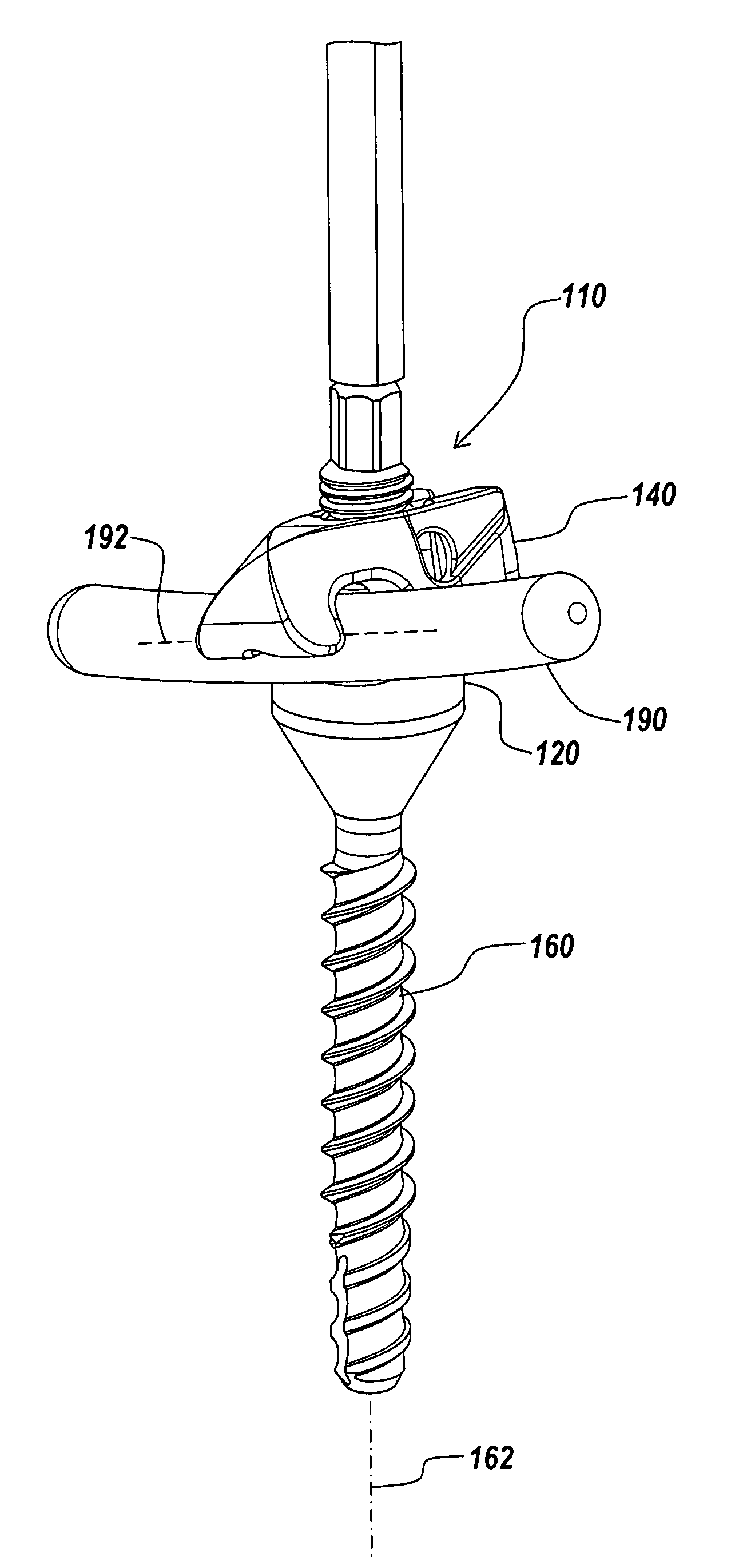
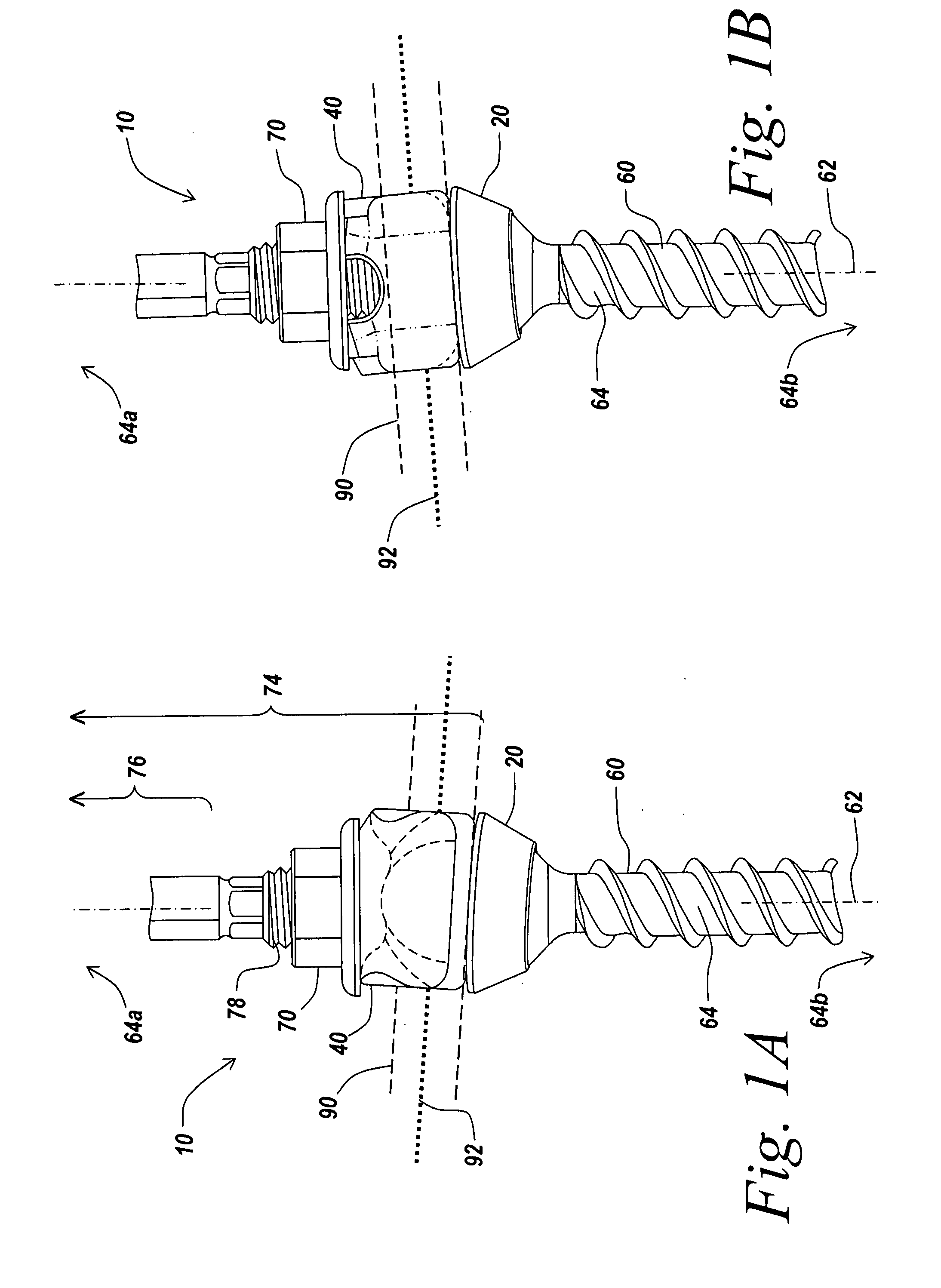
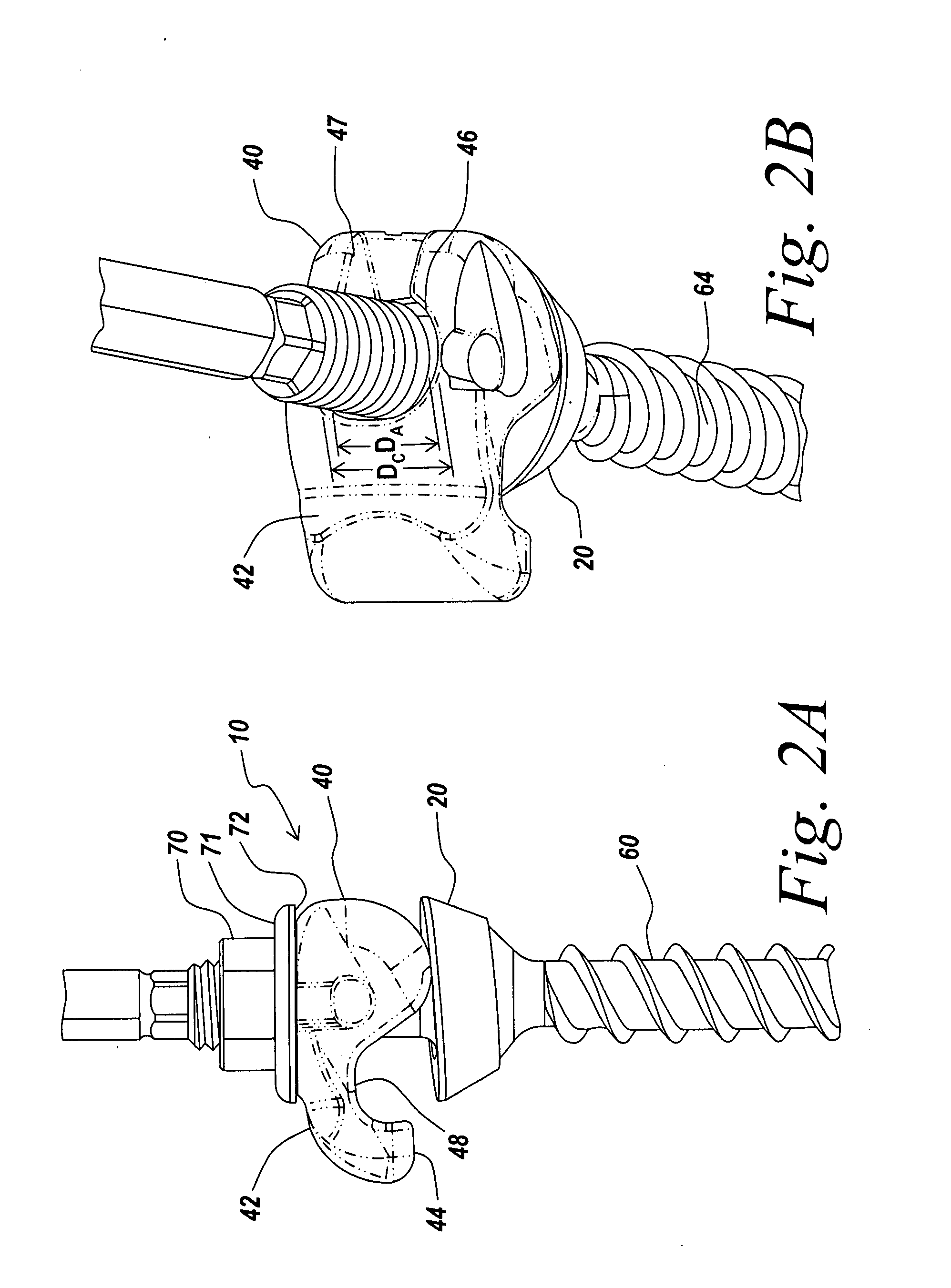
[0035]Certain exemplary embodiments will now be described to provide an overall understanding of the principles of the structure, function, manufacture, and use of the adaptable clamping mechanisms, bone anchor assemblies that include adaptable clamping mechanisms and methods disclosed herein. Examples of these embodiments are illustrated in the accompanying drawings. Those of ordinary skill in the art will understand that the adaptable clamping mechanisms and methods of use specifically described herein and illustrated in the accompanying drawings are non-limiting exemplary embodiments and that the scope of the present invention is defined solely by the claims. The features illustrated or described in connection with one exemplary embodiment may be combined with the features of other embodiments. Such modifications and variations are intended to be included within the scope of the present invention.

[0036]Exemplary embodiments described herein concern an adaptable clamping mechanism...


PUM


Abstract

An adaptable clamping mechanism for coupling an elongate spinal fixation element to a bone anchor is provided. A seat element and a clamp element of the adaptable clamping mechanism adapt to seat and clamp an elongate spinal fixation element whose longitudinal axis is non-perpendicular relative to the as central axis of the bone anchor. One or both of the seat element and the clamp element may adjust to an out-of-plane orientation of the elongate spinal fixation element by pivoting or rotating in one or more directions. One or both of the seat element and the clamp element may have a deformable portion configured to deform to the orientation of a surface of the elongate spinal fixation element. In addition, the seat element may be configured to provide tactile and / or auditory feedback to a surgeon when the seat element and the elongate spinal fixation element are in contact, facilitating proper positioning of the elongate spinal fixation element in the rod seat when using a minimally invasive rod-first surgical technique.

Description

FIELD OF THE INVENTION[0001]The present invention relates to a spinal connection device and method for use during orthopedic surgery. More particularly, the present invention relates to an adaptable clamping mechanism that couples an elongate spinal fixation element to a bone anchor.BACKGROUND OF THE INVENTION[0002]Spinal fixation systems may be used in surgery to align, adjust and / or fix portions of a spinal column, i.e., vertebrae, in a desired spatial relationship relative to each other. Many spinal fixation systems employ a spinal rod for supporting the spine and for properly positioning components of the spine for various treatment purposes. Vertebral bone anchors, comprising pins, bolts, screws, and hooks, engage the vertebrae and connect the supporting spinal rod to different vertebrae. Spinal fixation elements can be anchored to specific portions of the vertebra. Since each vertebra varies in shape and size, a variety of anchoring devices have been developed to facilitate en...

Claims


Application Information

Patent Timeline
Patent Type & Authority Applications(United States)
IPC IPC(8): A61B17/70A61B17/00A61B17/56A61B17/58
CPCA61B17/7011A61B17/7041A61B17/7037A61B17/705A61B17/7022
Inventor FRASIER, WILLIAM J.MAHONEY, MICHAELPAVENTO, NICHOLASRAMSAY, CHRISTOPHER L.ANDERSON, DAVID GREGLUDWIG, STEVEN
Owner DEPUY SYNTHES PROD INC
Why Eureka
Try Eureka