On-vehicle electronic device control system

Inactive Publication Date: 2009-03-05
DENSO CORP
View PDF8 Cites 4 Cited by
  • Summary
  • Abstract
  • Description
  • Claims
  • Application Information

AI Technical Summary

Benefits of technology

[0007]Therefore, an object of the invention is to provide an improved on-vehicle electronic device control system i

Problems solved by technology

As a result, if some coordination related trouble occurs in one of the layers, such trouble may spread over the

Method used


Image

  • On-vehicle electronic device control system
  • On-vehicle electronic device control system
  • On-vehicle electronic device control system

Examples


Example

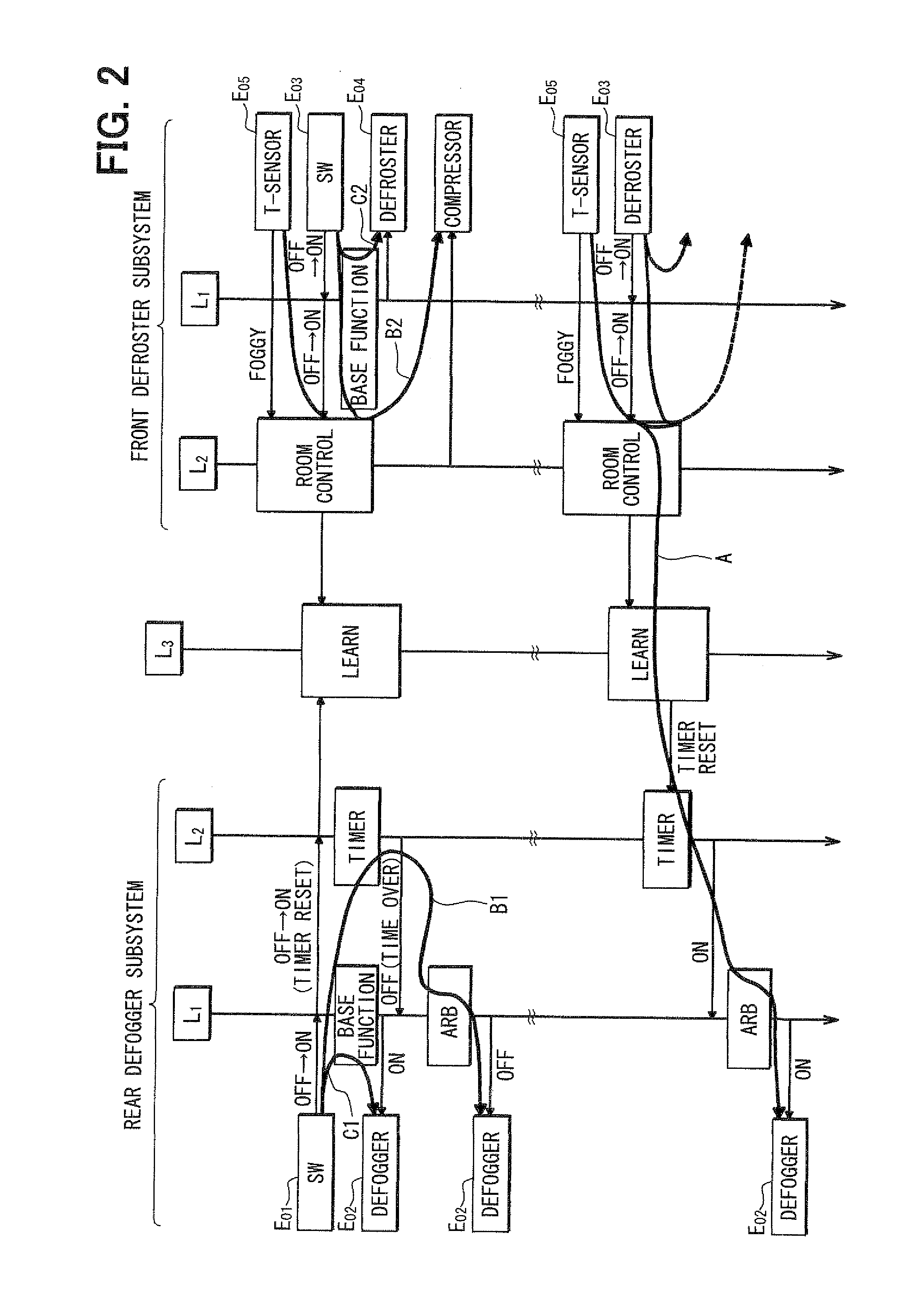
[0030]An on-vehicle electronic device control system according to the first embodiment of the invention is applied to a control of a defroster and a rear defogger, which will be described with reference to FIGS. 1-6.

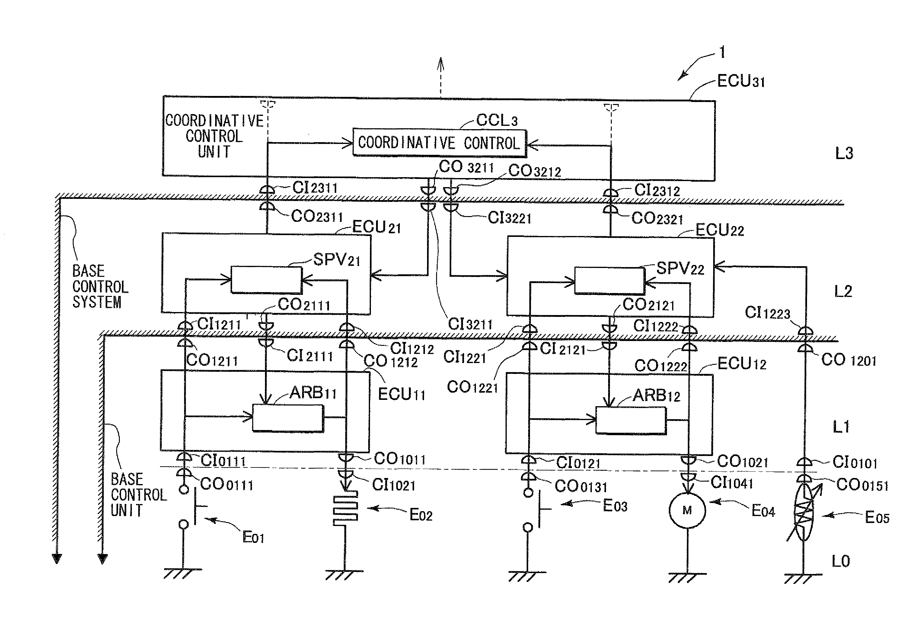
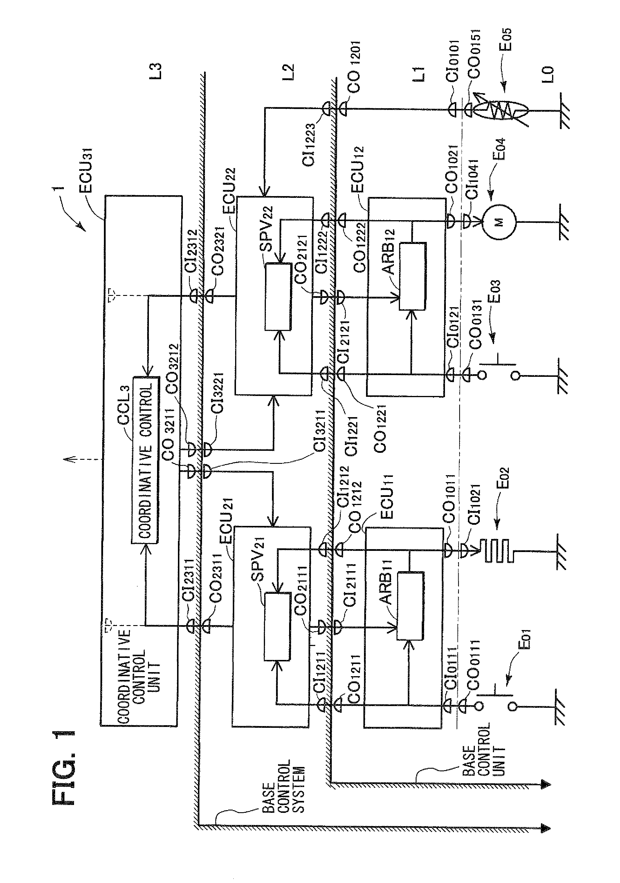
[0031]As shown in FIG. 1, the on-vehicle electronic device control system 1 includes a base device layer L0 that is disposed at the lowest layer of the system 1, a first control layer L1 that is disposed on the base device layer L0, a second control layer L2 that is disposed on the first control layer L1 and a third layer L3 that is disposed on the second control layer L2.

[0032]The base device layer L0 forms a front-end-input unit for a vehicle user and includes base input devices E01, E03 that provide higher control layers with base-control-input data and base-driven-devices E02, E04 that are automatically driven based on base-control-command data that are sent from the higher control layers L1-L3.

[0033]The first control layer L1 includes first control units ECU 11, ECU...

Example

[0057]An on-vehicle electronic device control system 2 according to the second embodiment of the invention that is applied to a smart entry system will be described with reference to FIGS. 7-8. The on-vehicle electronic device control system 2 includes a base control layer L0 on which base input devices, such as a door knob switch E01, a portable key (wireless switch) E02, a door-lock control switch E03 and a door-lock position detecting switch E05 and base driven devices, such as a modulating-demodulating unit MODEM 112 (in the portable key E02), a door-lock motor E04 and a door-lock-mechanism-side data transmission unit E06, are disposed and three layers L1-L3 on which first control units ECU 11, ECU 12, ECU 13, second control units ECU 21, ECU 22 and a third control unit ECU 31 are disposed. Each of the first, second and third control units ECU 11, ECU 12, ECU 13, ECU 21, ECU 22 and ECU 31 has a lower-to-higher-layer control-command data input portion and a higher-to-lower-layer ...


PUM


Abstract

An on-vehicle electronic device control system includes a base-device-layer on which base-inputting-devices and base-driven-devices are disposed and plural control layers on which plural control units are disposed. Each of the control units has a lower-to-higher-layer-data-input-portion for inputting data from a lower layer and a higher-to-lower-layer-data-output-portion for outputting control-command-data to a lower layer. At least one of the control units disposed on one of the control layers has a higher-to-lower-data-input-portion for inputting data from a higher layer. At least one of the control units disposed on one of the control layers has a lower-to-higher-data output-portion for outputting data to a higher layer and one of the control units that has the higher-to-lower-data-input-portion functions as a coordinative-control-command-unit that determines output data based on both data inputted thereto from a higher layer and input data from a lower layer and also functions as an autonomous-control-command-unit that determines the output data based only on the input data from the lower layer if the input data from the higher layer are stopped.

Description

CROSS REFERENCE TO RELATED APPLICATION[0001]The present application is based on and claims priority from Japanese Patent Application 2007-223074, filed Aug. 29, 2007, the contents of which are incorporated herein by reference.BACKGROUND OF THE INVENTION[0002]1. Field of the Invention[0003]The present invention relates to an electronic equipment control system that is mounted in a vehicle.[0004]2. Description of the Related Art[0005]The number of various kinds of electronic devices that are mounted in a vehicle to provide various kinds of functions has increased year by year. In order to effectively utilize the functions, it has been required interface structures. In order to meet demand for inexpensive devices having high performance, system sharing among various vehicles and coordination among various systems have been adopted. For example, JP-A-2006-142994 discloses a hierarchical system architecture, in which various kinds of system hardware and software are formed into an applic...

Claims


Application Information

Patent Timeline
IPC IPC(8): G01M17/00G06F19/00B60R16/02B60R16/023H04L69/40B60R25/01B60R25/04B60R25/24
CPCB60W50/04
Inventor SAKANE, HIROYUKI
Owner DENSO CORP
Why Eureka
Try Eureka