
Circuit and Method for Fitting the Output of a Sensor to a Predetermined Linear Relationship

a technology of linear relationship and output, applied in the direction of amplifiers, transmission, electrical/magnetic means, etc., can solve the problems of significant error in estimated temperature, significant measurement error, and significant parasitic leakage resistance in the circui

Inactive Publication Date: 2009-03-05
RENNEBERG CARL PETER
View PDF8 Cites 33 Cited by
  • Summary
  • Abstract
  • Description
  • Claims
  • Application Information

AI Technical Summary

Benefits of technology

[0024]In a third aspect of the invention, there is provided a first circuit in accordance with any one of the preceding aspects of the invention, wherein...

Problems solved by technology

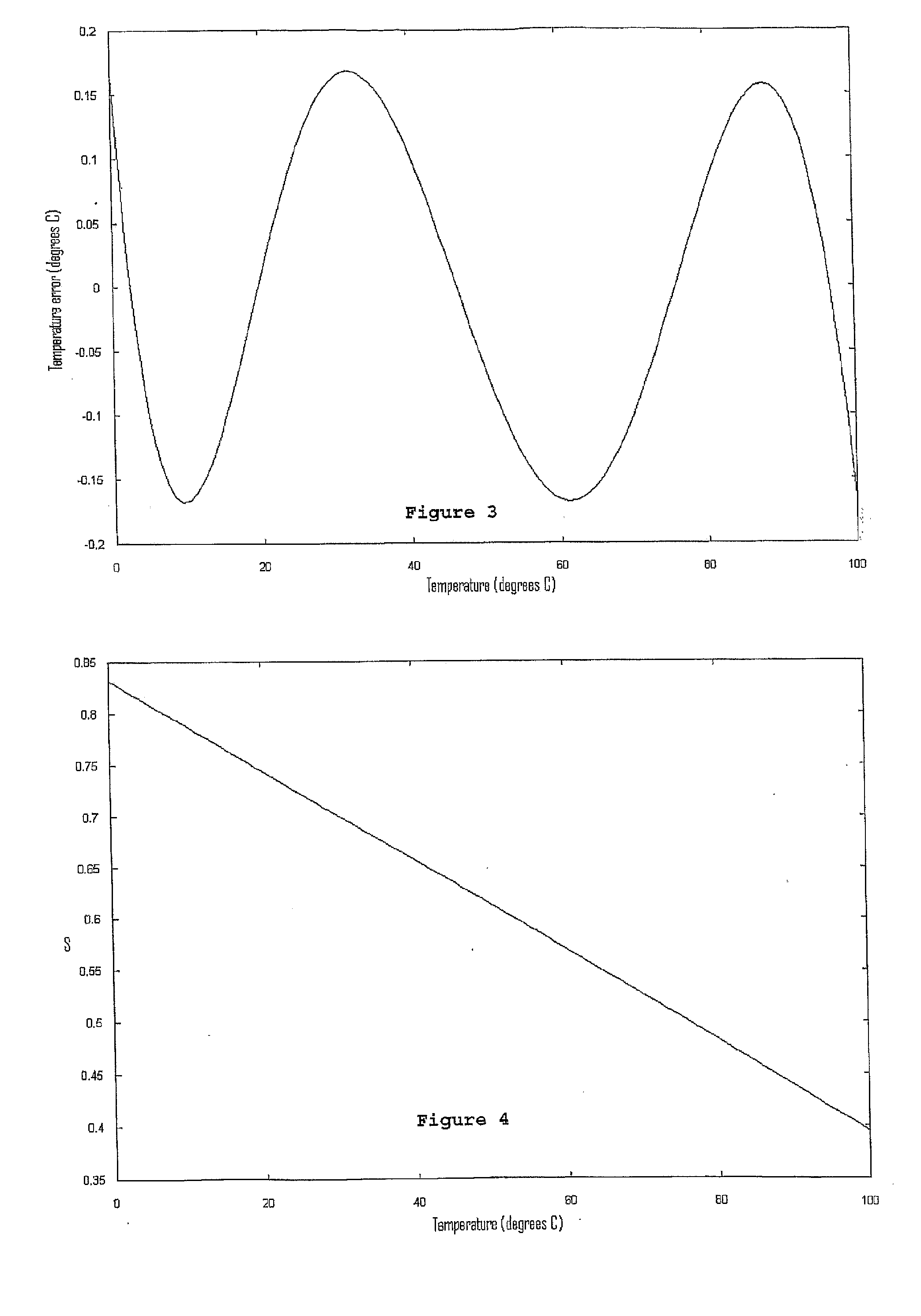
The choosing of values of components and circuit parameters may also be approached as an optimization problem, where the objective is to minimise the error (“approximation error”) between a transfer function of the circuit and a desired mathematical relationship.
However, in the case of FIG. 9, the values of slope m and offset c in the desired linear relationship must be optimized, so generally they cannot be specified explicitly beforehand.
If the resistors used in the circuit are low, for example a few hundred ohms, then the parasitic series resistances, in the thermistor leads and other circuit connections, can lead to significant measurement errors.
If the resistors used in the circuit are high, for example, 10 Mohms, then significant parasitic leakage resistances may occur in the circuit.
The parasitic leakages may cause significant errors in the estimated temperature.
Once again, the implementation has similar temperature characteristics and similar peak linearity error, but has a lower resistance spread.
This flexibility comes at the cost of using additional devices, such as FETs.
This change, in combination with the choice of scaling factors, produces a smaller error than the prior art circuit.
Such an arrangement increases the circuit's rejection of signals induced into the thermistor connections by external interfering sources.
For some embodiments using frequency domain techniques, it may not be possible to express the circuit's output in this manner: the output may be a non-linear function in terms of some parameter or physical property P. However, in practice, the 2*n+2 alternation principle still applies to embodiments involving non-linear approximation—one best matches the desired output characteristic, in a minimax sense, when the error curve has at least 2*n+2 alternations.

Method used


Image

  • Circuit and Method for Fitting the Output of a Sensor to a Predetermined Linear Relationship
  • Circuit and Method for Fitting the Output of a Sensor to a Predetermined Linear Relationship
  • Circuit and Method for Fitting the Output of a Sensor to a Predetermined Linear Relationship

Examples


Embodiment Construction

Introduction

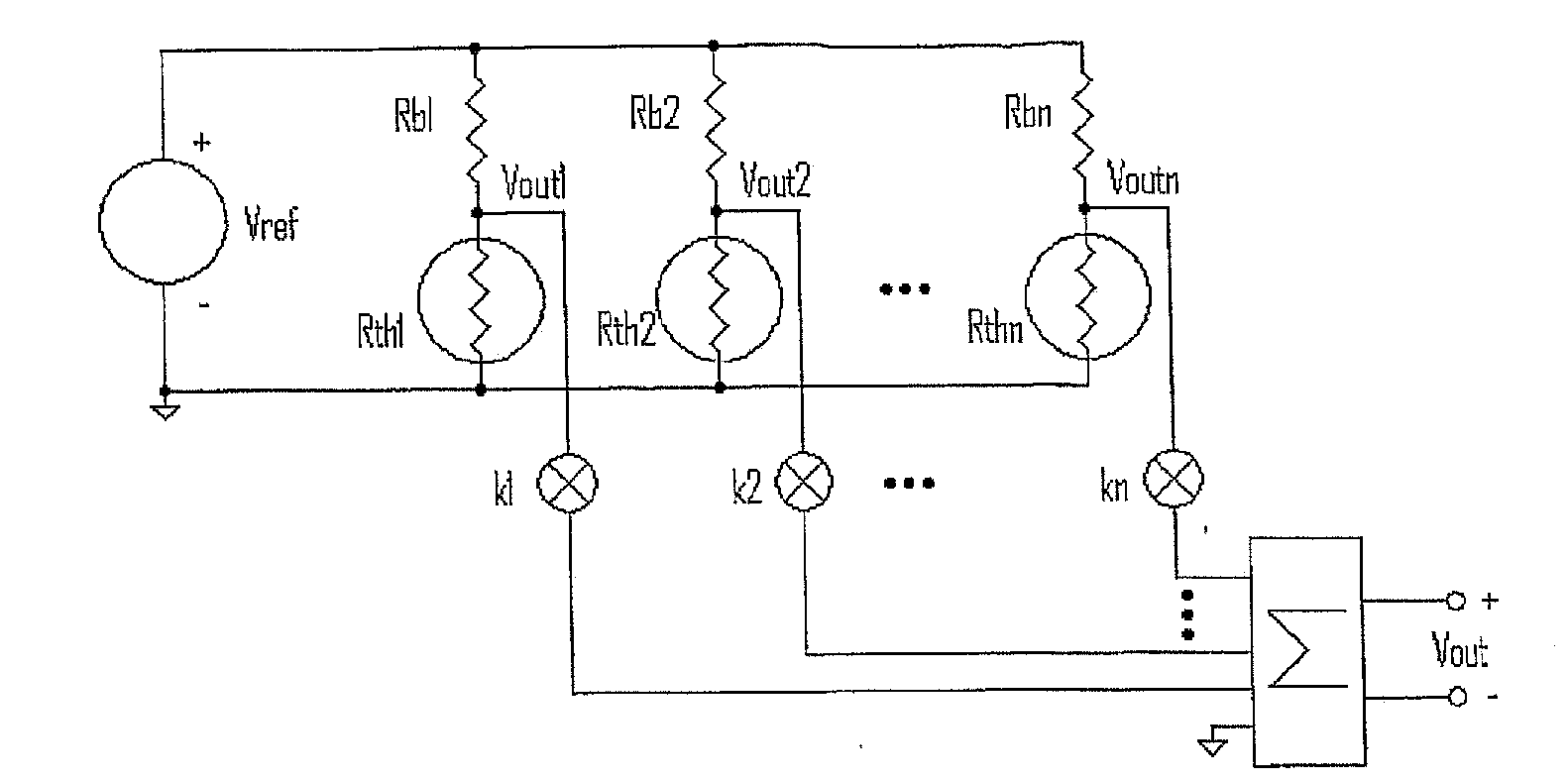
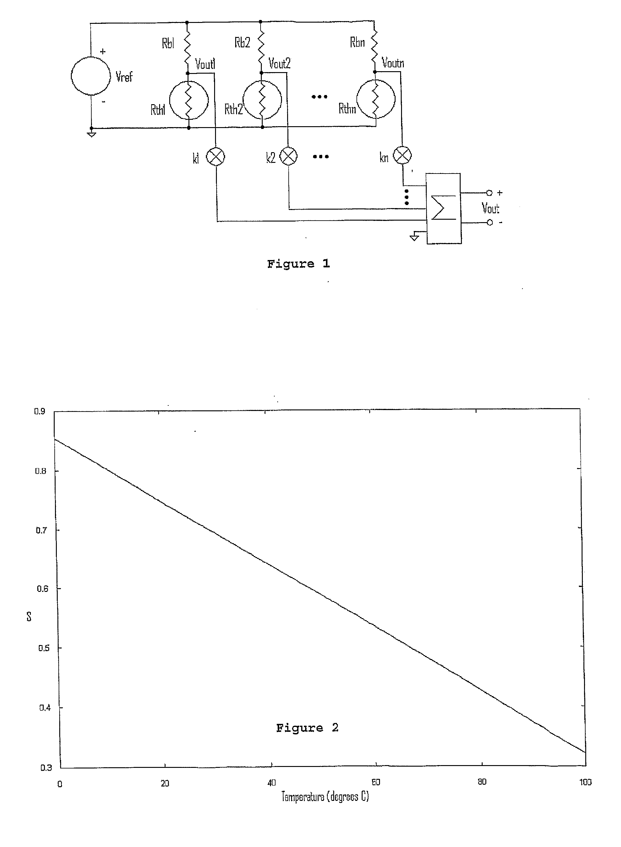
[0194]In a simple well-known prior art sensor circuit, there is included a resistive temperature sensor in the form of a thermistor, a power source, and a resistor which, in combination with the sensor, forms a voltage divider circuit. The voltage at the junction of the resistor and sensor is a function of the internal resistance of the sensor and the resistor. As the temperature of the sensor changes, the internal resistance of the sensor changes and so the output voltage also changes.

[0195]However, the relationship between temperature change and output voltage is not linear. In many applications, one desires a linear (or some other) relationship.

[0196]The present invention, in at least some embodiments, achieves the desired linearity by providing an electronic circuit for biasing and interfacing with a sensor such that the sensor's parameters or output signal varies with respect to a physical property P, where the output of the circuit can be expressed as a rational fu...


PUM


Abstract

A circuit employing a plurality of n sensors, the circuit being arranged such that one of a transfer function or output function of the circuit approximates a desired mathematical relationship between a physical property measured by the sensors and the output of the circuit, the one of the transfer function or output function equalling the desired relationship at least 2*n+1 points.

Description

FIELD OF THE INVENTION[0001]The present invention relates to circuits and methods for generating an output with a predetermined characteristic, from one or more sensors, such as temperature sensors. The present invention may also find application in the compensation of circuits such as, but not limited to, temperature compensation.BACKGROUND OF THE INVENTION[0002]Electronic sensors are devices whose electrical properties change in a significant, repeatable manner under the influence of a physical property, such as ambient temperature. A great variety of sensors known in the art are nonlinear.[0003]In many applications, one desires the sensor, or a circuit employing the sensor, to generate an output signal that varies in a linear manner with respect to the physical property. Circuits that perform this role are referred to as linearization circuits.[0004]In many applications, it is more practical and effective to use a non-linear sensor in conjunction with a linearization circuit, tha...

Claims


Application Information

Patent Timeline
IPC IPC(8): G06F15/00G01R13/00G01D3/02
CPCG01D3/02G01K7/25G01K7/22G01K1/026
Inventor RENNEBERG, CARL PETER
Owner RENNEBERG CARL PETER
Learn More