Check matrix generating method, encoding method, decoding method, communication device, encoder, and decoder
a matrix and matrix technology, applied in the field of encoding technology in digital communications, can solve problems such as performance degradation generally
- Summary
- Abstract
- Description
- Claims
- Application Information
AI Technical Summary
Benefits of technology
Problems solved by technology
Method used
Image
Examples
first embodiment
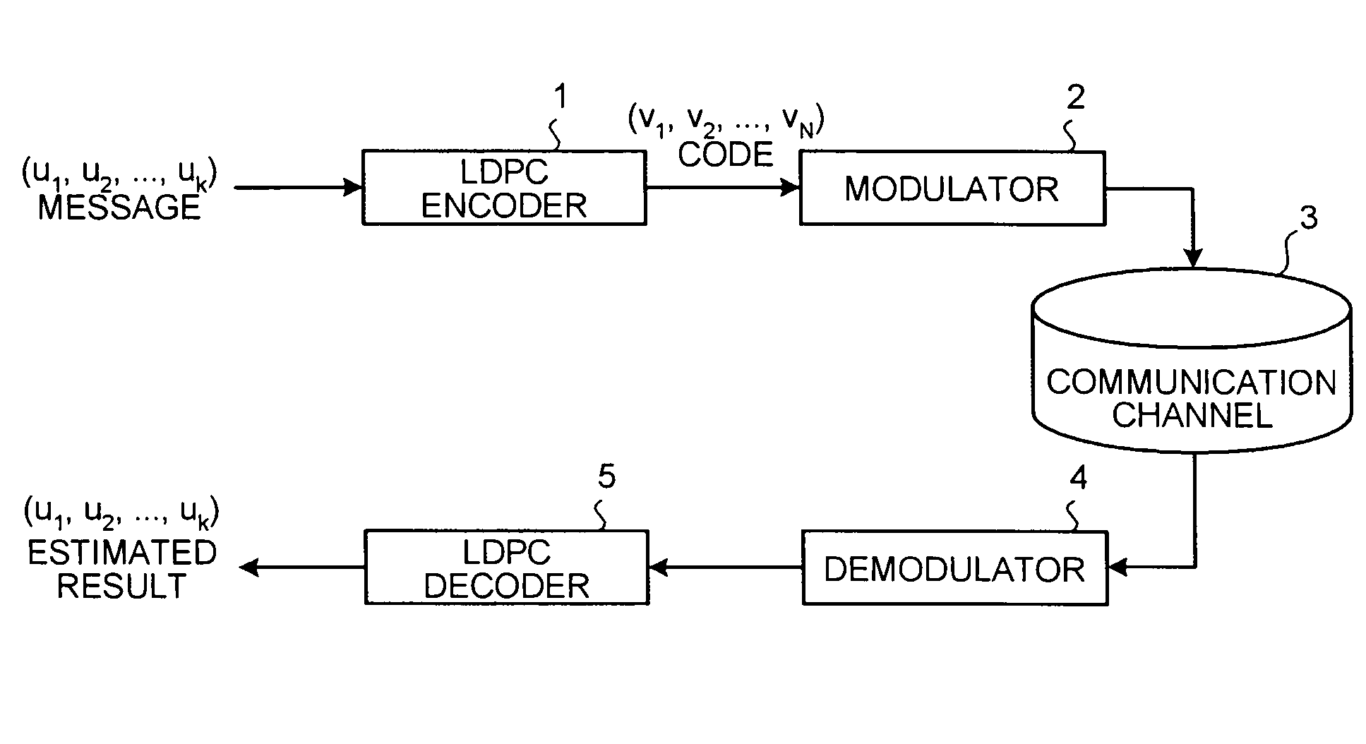
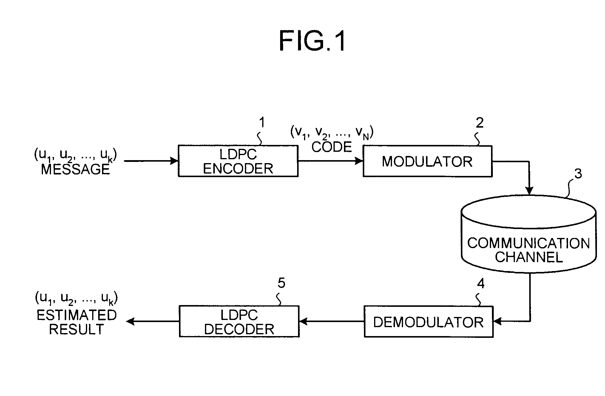
[0047]FIG. 1 is a schematic diagram illustrating a configuration example of a communication system including an LDPC encoder and an LDPC decoder according to the present embodiment. In FIG. 1, a communication apparatus (which is called a transmission apparatus) on a transmission-side has a configuration including an LDPC encoder 1 and a modulator 2, and a communication apparatus (which is called a reception apparatus) on a reception-side has a configuration including a demodulator 4 and an LDPC decoder 5.
[0048]Here, a flow of encoding processing and decoding processing in the communication system that employs LDPC codes will be explained briefly.
[0049]The LDPC encoder 1 in the transmission apparatus generates a parity check matrix generated by a check-matrix generating method according to the present embodiment, namely, a parity check matrix HM with M-row×N-column to which masking processing is performed based on a predetermined masking rule described below.
[0050]Thereafter, the LDP...
second embodiment
[0103]Next, a code configuration method according to a second embodiment will be explained below. Here, processing different from that of the first embodiment will be explained.
[0104]When p (an odd number or a prime number other than 2) of the cyclic permutation matrices in the parity check matrix for the LDPC codes is set to be variable, data length K=p×r (r is the number of unit matrices: r=36 in the first embodiment) can be set to be variable. Meanwhile, if the data length K cannot be represented by p×r, the code is formed as shown in FIG. 8.
[0105]For example, the LDPC encoder 1 selects an integer value obtained by rounding up K / r for p, sequentially inserts the known value “0” or “1” in bits corresponding to portions with the heavy column degree in the parity check matrix by the number of “(integer p obtained by rounding up K / r)×r−K”, and encodes them. The decoding side determines the known value “0” or “1” for the values corresponding to the same bits in the parity check matrix...
third embodiment
[0110]Next, a code configuration method according to a third embodiment will be explained below. Here, processing different from the processing of the first and the second embodiments will be explained.
[0111]When p (an odd number or a prime number other than 2) of the cyclic permutation matrices in the parity check matrix for the LDPC codes generated in the first embodiment is set to be variable, data length K=p×r (r is the number of unit matrices: r=36 in the first embodiment) can be set to be variable. Meanwhile, if the data length K cannot be represented by p×r, the code is formed as shown in FIG. 9.
[0112]For example, the LDPC encoder 1 selects an integer value obtained by rounding up K / r for p, sequentially inserts the known value “0” or “1” in bits corresponding to portions with light column degrees of data bit portion (bit portion corresponding to columns in the matrix HMQC after masking processing) in the check matrix by the number of “(integer p obtained by rounding up K / r)×...
PUM
 Abstract
Description
Claims
Application Information
 - R&D
- Intellectual Property
- Life Sciences
- Materials
- Tech Scout
- Unparalleled Data Quality
- Higher Quality Content
- 60% Fewer Hallucinations
Browse by: Latest US Patents, China's latest patents, Technical Efficacy Thesaurus, Application Domain, Technology Topic, Popular Technical Reports.
© 2025 PatSnap. All rights reserved.Legal|Privacy policy|Modern Slavery Act Transparency Statement|Sitemap|About US| Contact US: help@patsnap.com


