
Method for mounting a motor vehicle door lock

a technology for motor vehicles and door locks, applied in the field of can solve the problems of difficulty in finding the inside locking lever, usually takes a considerable and the mounting of the known motor vehicle door locks, so as to speed up the mounting process and reduce the amount of skill and practice required

Active Publication Date: 2009-03-12
BROSE SCHLIESSSYSTEME GMBH & CO KG
View PDF41 Cites 16 Cited by
  • Summary
  • Abstract
  • Description
  • Claims
  • Application Information

AI Technical Summary

Benefits of technology

[0007]A primary object of the present invention is directed to providing a method for mounting a motor vehicle door lock to a motor vehicle door that speeds up the mounting process, and at the same time, reduces the skill and practice necessary for mounting of the motor vehicle door lock.
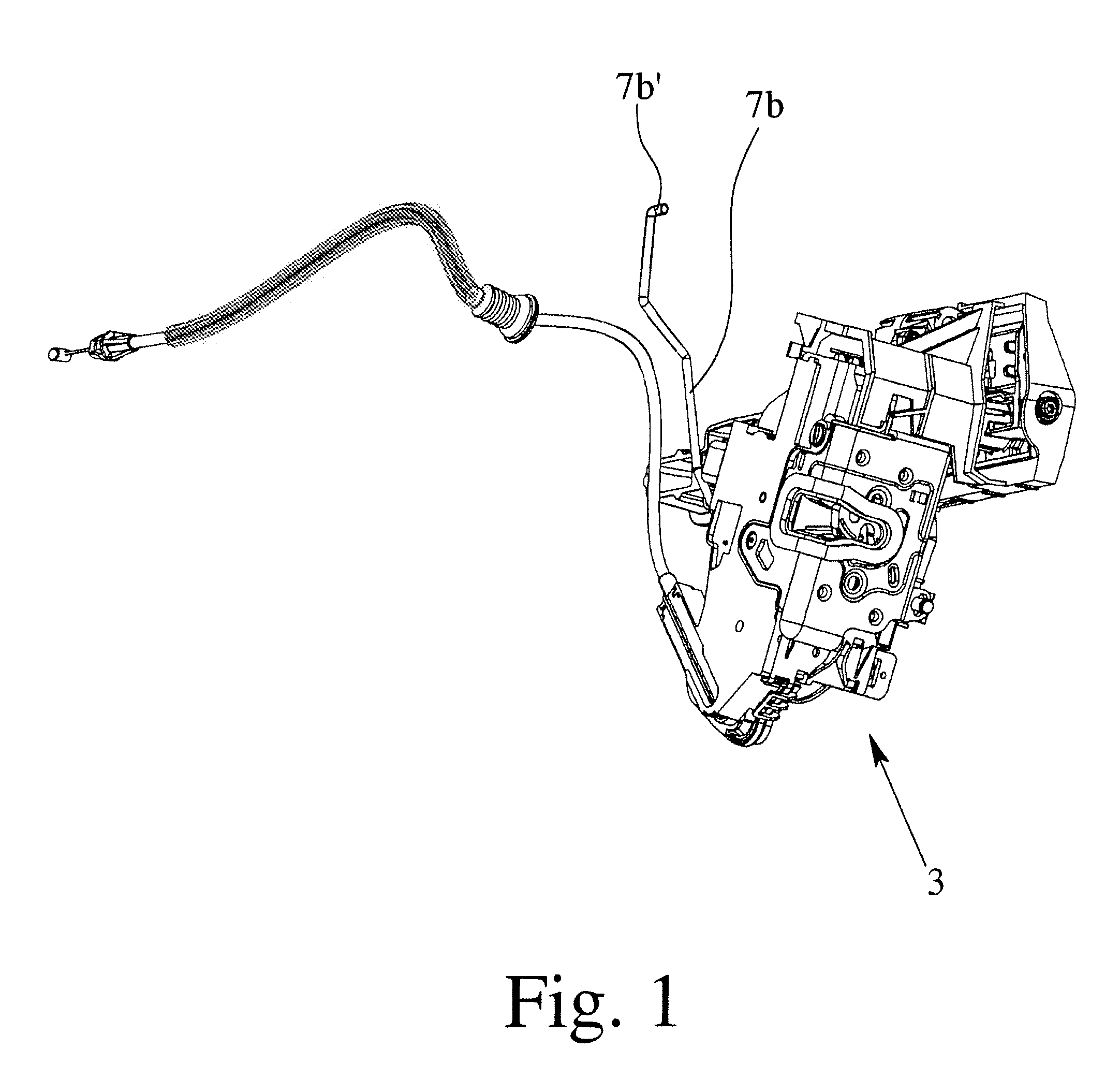
[0008]It is essential for the teaching of the present invention that the connecting rod between the inside locking lever and the inside safety element is at least a two part component comprising an upper connecting rod and a lower connecting rod. After coupling of the lower connecting rod to the inside locking lever, the motor vehicle door lock is moved into the hollow space, thereby guiding the lower connecting rod through the passage opening. This can easily be done due to the reduced length of the lower connecting rod. Next, the connecting rod is completed by coupling the upper connecting rod to the lower connecting rod at a coupling position, which is outside the hollow space in proximity of the passage opening.

Problems solved by technology

Mounting of the known motor vehicle door lock always leads to problems.
If the motor vehicle door lock is to be mounted while the connecting rod is already coupled to the inside locking lever, it normally takes a considerable amount of skill and practice to find the respective passage opening in the wall segment of the door body due to the large extension of the connecting rod.
If the connecting rod is to be coupled to the motor vehicle door lock after the lock has been mounted, finding the inside locking lever is generally even harder.
Another drawback of the known arrangement is the fact that, normally, the part of the connecting rod that, in the mounted condition, is located outside the hollow space is normally of considerable length.
In many cases this leads to the necessity of a large mounting opening within the door body as the lock has to be moved over an accordingly large distance in mostly vertical direction.

Method used


Image

  • Method for mounting a motor vehicle door lock
  • Method for mounting a motor vehicle door lock
  • Method for mounting a motor vehicle door lock

Examples


Embodiment Construction

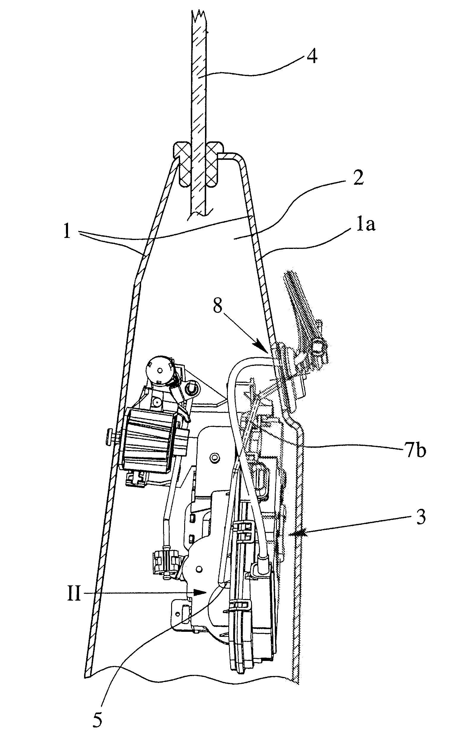
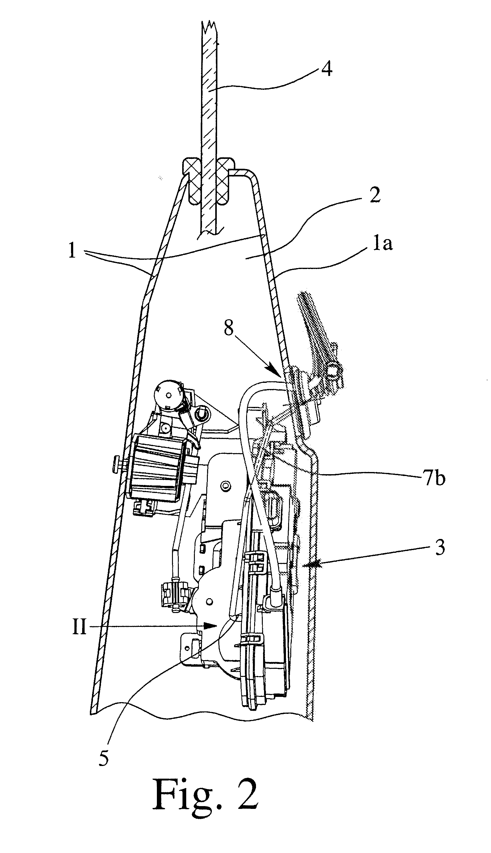
[0019]The motor vehicle door shown in FIG. 4 comprises a door body 1 enclosing a hollow space 2 in which a motor vehicle door lock 3 is situated in its fully mounted condition. A window 4 is shown that may be moved further into the hollow space 2 by a respective mechanism. The window 4, however, is not relevant for the present invention.

[0020]The motor vehicle door lock 3 comprises an inside locking lever 5 that is part of the lock mechanism. The inside locking lever 5 is coupled to an inside safety element 6 via a connecting rod 7. The inside safety element 6 is located in such a way that it is actuatable by a passenger sitting inside the motor vehicle. By this activation, the motor vehicle door lock 3 may be switched into the locked and into the unlocked state.

[0021]The door body 1 has a wall segment 1a which separates the hollow space 2 from the passenger compartment. It is to be understood that this expression presently has a broad meaning. For example additional panel elements ...


PUM

PropertyMeasurementUnit
lengthaaaaaaaaaa
distanceaaaaaaaaaa
areaaaaaaaaaaa

Abstract

A motor vehicle door and to a motor vehicle door lock and a method for mounting the motor vehicle door lock in a motor vehicle door, the motor vehicle door lock having an inside locking lever, and when installed, being located in a hollow space of the door and coupled to an inside safety element via a connecting rod that extends through a passage opening in an inside wall segment of the door body. To facilitate installation, the connecting rod is formed of two segments, a lower connecting rod segment extending through the passage opening and being connected to a an upper connecting rod segment at a location that is outside of the hollow space in proximity to the passage opening.

Description

BACKGROUND OF THE INVENTION[0001]1. Field of the Invention[0002]This invention relates, generally, to a method for mounting a motor vehicle door lock to a motor vehicle door. The motor vehicle door lock comprises an inside locking lever that, in the mounting condition, is coupled to an inside safety element via a connecting rod. Also, this invention relates generally to a motor vehicle door and to a motor vehicle door lock.[0003]2. Description of Related Art[0004]Known motor vehicle doors comprise a door body providing a hollow space, in which the motor vehicle door lock is situated. Such an arrangement is shown in German Patent DE 25 22 301 C3. The motor vehicle door lock disclosed in this patent comprises an inside locking lever that, in the mounted condition, is coupled to an inside safety element via a connecting rod. The inside safety element may be actuated by a passenger who is sitting inside the motor vehicle in order to lock or unlock the door lock. The door body has a wall...

Claims


Application Information

Patent Timeline
Patent Type & Authority Applications(United States)
IPC IPC(8): B60J5/00B23P11/00E05C3/00
CPCB60J5/00Y10T29/49947E05B85/08E05B79/04Y10T292/1047
Inventor KELLER, PETER OLIVERHUISMAN, WARREN
Owner BROSE SCHLIESSSYSTEME GMBH & CO KG
Learn More